Bridgeport Project

PeterT

Ultra Member
Premium Member
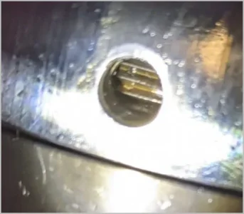
I'm wondering if the inner set screw wasn't actually put in properly and catching on the nose cover? I wonder how they even managed to get the cover on at all...

View attachment 16021

That's exactly what I was wondering - if outer set screw C has migrated outward or somehow installed just a but proud & catching the nose cap ID. I cant think of any way to remove them from inside the quill unless they happen to be dead loose, nothing to wrench onto. Lets think happy thoughts for now & assume its the main nose cap threads or some crap has migrated down.

Gentle heat around the thread area might work, sometimes just a bit of expansion is enough to get rotation started & break the rust glue or whatever is holding it firm. I'm not sure if there is a rubber seal in there or not. Trouble is the heat will go right through the mated threads & expand the nose cap almost as fast. I almost wonder if you wouldn't be better off with a strap wrench around the cap & snipe bar for leverage & try & give it a jerk vs pure torque applied through the pin wrench?

When I assembled mine I put a thin smear of anti-seize on the threads thinking I was anal, now I'm kind of glad. But that set screw against the threads business has always bugged me. It should have a deformable lead slug or something as someone mentioned.
 

Susquatch

Ultra Member
Administrator
Moderator
Premium Member
When I assembled mine I put a thin smear of anti-seize on the threads thinking I was anal, now I'm kind of glad. But that set screw against the threads business has always bugged me. It should have a deformable lead slug or something as someone mentioned.

You mentioned this before.

My nose cap DOES NOT HAVE a set screw AGAINST THE THREADS. The set screw has a particular spot on the nose cap threads that it is designed to fit into. It is a recessed pocket in the threads of the quill. Here is a photo.

20210711_135614.jpg

For now, I have a sharpie mark on the nose cap so I know where the recess is so I can align it with the set screw on the quill. I will put a punch mark there after I decide which mill to keep.

I totally agree with your concern though. It bothers the daylights out of me to tighten any lock screw against any threads too. And no offense intended, but I don't like the lead ball approach either.

Any time I have ever encountered that, I have tried to design something to do the same thing without the screw mashing against threads. I've been doing this with my stuff for over 40 years. Ever since the first time I got seriously bitten by this design flaw. And that's what I call it - a design flaw. Set screws should NEVER engage in the threads of anything!

My favorite method is to use split rings where I can. These are basically a regular lock ring with a split in it. The split is then drilled side-to-side and then tapped for a small Allen screw which draws the split together tightening the lock ring in place.

Here is an example. The original lock ring on the right and the replacement on the left.

20210711_153257.jpg

Of course you can't really do that with the nose cap. But I'm fine with the recessed pocket for the set screw.
 

Brent H

Ultra Member
For the Bridgeport: original from the factory the end cap was tightened on and then a recess drilled into the spindle (as you can see on the nose cap previously pictured). Depending on the age of the mill and the repairs made, there may be several “detents” drilled for the location of the set screw.
The nose cap should be snug and the set screw just needs to be in place to lock the thread but certainly not to mash it.

If you tighten the set screw “solid” on to the threads you will ever so slightly warp the spindle and it will work like crap in the last couple inches of travel.

In this application, as a lock, I see nothing wrong with the design or function. For my particular mill (I have the QC 30 design)there is no real stress or strain on the nose piece to cause concern even if the screw was not there.

Be careful using the original “detent” as a “tighten up to here” spot as it may or may not work out if you change bearings.
 

Susquatch

Ultra Member
Administrator
Moderator
Premium Member
For the Bridgeport: original from the factory the end cap was tightened on and then a recess drilled into the spindle (as you can see on the nose cap previously pictured). Depending on the age of the mill and the repairs made, there may be several “detents” drilled for the location of the set screw.
The nose cap should be snug and the set screw just needs to be in place to lock the thread but certainly not to mash it.

If you tighten the set screw “solid” on to the threads you will ever so slightly warp the spindle and it will work like crap in the last couple inches of travel.

In this application, as a lock, I see nothing wrong with the design or function. For my particular mill (I have the QC 30 design)there is no real stress or strain on the nose piece to cause concern even if the screw was not there.

Be careful using the original “detent” as a “tighten up to here” spot as it may or may not work out if you change bearings.

Great advice as always @Brent H!

Will do!

That said, I still don't like set screws bearing on threads. It's just the whole principle of it even if it is ok. But I do like the retention detent/recess just fine. I doubt I'll be into the spindle bearings even if I do keep the Bridgeport, but you never know....... Forewarned is forearmed.

Thanks!
 

PeterT

Ultra Member
Premium Member
My nose cap DOES NOT HAVE a set screw AGAINST THE THREADS. The set screw has a particular spot on the nose cap threads that it is designed to fit into. It is a recessed pocket in the threads of the quill. Here is a photo.

I think there are too many Bridgeport spindle nose caps being discussed for my simple brain so I'll be quiet now LoL. I assumed pic in post #153 was the stuck troublemaker & to my eye, peeking through the hole, does not look like it has a recess drill for the set screw like your pic - unless the nose cap has somehow been rotated beyond that location or something preventing it from arriving to that location. Good luck boys.
 

Attachments

  • SNAG-2021-07-11 6.49.52 PM.jpg
    SNAG-2021-07-11 6.49.52 PM.jpg
    23.2 KB · Views: 5
  • SNAG-2021-07-11 6.51.00 PM.jpg
    SNAG-2021-07-11 6.51.00 PM.jpg
    18 KB · Views: 5

architect

Super User
I think there are too many Bridgeport spindle nose caps being discussed for my simple brain so I'll be quiet now LoL. I assumed pic in post #153 was the stuck troublemaker & to my eye, peeking through the hole, does not look like it has a recess drill for the set screw like your pic - unless the nose cap has somehow been rotated beyond that location or something preventing it from arriving to that location. Good luck boys.

My pic is after I've rotated my cap 1/4 turn already so the recess would not be visible. I'll take a final photo after I manage to get the cap off.
 

architect

Super User
Was able to exert more force with the help of my friend standing on the house. But the nose cover has defeated the plywood-Excalibur... I have been stuck on this for too long and will just come back to in the future once it's all reassembled again.

PXL_20210712_211816776.jpg


PXL_20210712_211810597.jpg

PXL_20210712_211913323.jpg
 

JamHandy

(Mark)
So what I want to ask is, does the set screw guide for the tool holder look sheared off? Or does it look like it’s backed out flush with the bore and pressing against the nose piece threads?
 

Brent H

Ultra Member
Sheared clean off - R8 collet must have spun - should still be able to get the nut off - just might need a bigger boat - er….tool … LOL.
 

Susquatch

Ultra Member
Administrator
Moderator
Premium Member
..... I have been stuck on this for too long and will just come back to in the future once it's all reassembled again.

I'd be scared of waiting that long. What if you need to take it all apart again to do that?

I'd be mounting it back on the head right now if I were you so you can get some leverage on it.

Also, it's apparent to me that you need to make a steel tool on your lathe. A round collar to barely clear the spindle with drilled and tapped holes to take 1/4" grade 5 Bolts with the noses turned down to fit the spanner holes, and two 1/2" tapped holes on the sides to take regular 1/2" bolts that serve as handles would get the job done.

Perhaps easier would be a big nut chucked on the lathe and then bore the center out to clear the spindle nose. Then drill and tap for 1/4" grade 5 Bolts as above. The difference being the ability to put a big wench (pun intended) on it! Big nuts like that are available at most farm supply outlets.

I can't wait till we can use our own mills to make stuff like that!

Let me know if that description isn't clear enough and I'll sketch it up for you.

Also thinking that might take a hammer obviating the need to put it back on your mill head....
 

architect

Super User
The quill assembly slips right out from the housing without needing disassembly so should be fine. I also mean just continue to go through the rest of the quill housing work.

The leverage isn't the issue. You can see that we've applied so much force that the plywood has failed. JamHandy will rig a metal tool together. And if THAT fails, then I'm taking the quill assembly to see Brent!
 

Susquatch

Ultra Member
Administrator
Moderator
Premium Member
The quill assembly slips right out from the housing without needing disassembly so should be fine. I also mean just continue to go through the rest of the quill housing work.

The leverage isn't the issue. You can see that we've applied so much force that the plywood has failed. JamHandy will rig a metal tool together. And if THAT fails, then I'm taking the quill assembly to see Brent!

Sounds like a plan.

Wish you lived closer. I'd be more than happy to help. I'm sure I'd also learn things in the process.

Gunna make myself that big nut tool just cuz I can. Prolly don't need it - especially AFTER I make it - but it'll be good preventative insurance......

Waiting on a motor and a rebuild kit from H&W for my step pulley head. So good time to make a cool tool.
 
Last edited:

cuslog

Super User
Premium Member
Kinda late to the party here but thought I'd show a couple pictures of a tool I made to get my spindle nose off - maybe it'll help someone next time. Just a little different pin wrench - gotta make it before you take the mill apart (or on your spare mill). Thick enough to get a big pipe wrench on. SHCScrews spaced appropriately and turned down to correct dia. Trap the tool between the quill nose and your vise or the table - insert a couple business cards under so you don't scar vise or table. Remove horizontal set screw as well as the grub screw. Mine was right hand thread (chinese clone) others could be left so don't get too angry with it too soon. Now you've got something trapped in there that won't slip and you can really get some force on it without damaging anything. Save it for next time ! PICT0100.JPG PICT0101.JPG
 

Susquatch

Ultra Member
Administrator
Moderator
Premium Member
Kinda late to the party here but thought I'd show a couple pictures of a tool I made to get my spindle nose off - maybe it'll help someone next time. Just a little different pin wrench - gotta make it before you take the mill apart (or on your spare mill). Thick enough to get a big pipe wrench on. SHCScrews spaced appropriately and turned down to correct dia. Trap the tool between the quill nose and your vise or the table - insert a couple business cards under so you don't scar vise or table. Remove horizontal set screw as well as the grub screw. Mine was right hand thread (chinese clone) others could be left so don't get too angry with it too soon. Now you've got something trapped in there that won't slip and you can really get some force on it without damaging anything. Save it for next time ! View attachment 16068View attachment 16069

Same principal as my bored out nut except you intend it to be used with a pipe wrench and I intend to use mine with a socket or open end wrench.

What I really like about your concept is the application method. By pinching the device against the table or a vice, you significantly reduce (or even eliminate) off axis forces so it becomes a pure torque. VERY COOL!

Never saw a Socket Head Machine Screw called an "SHMScrew" before either.

I love learning new things and seeing new ideas!
 

JamHandy

(Mark)
Now there’s a tool, @cuslog ! I’m a little embarrassed @architect showed off my wooden jobbie like that. It was quick and dirty and I didn’t realize just how stuck the piece was. I figured on a bit of leverage at first to unbind it, then spin it off by hand.
The last thing a guy wants to be known for on a metal working forum is his wooden tools. :)
 

Brent H

Ultra Member
@JamHandy : have a watch of this video:


At the end you will see Barry hammer the end nut back on with a spanner and a decent size dead blow hammer. The quill housing is held in copper jaws in a sizeable vice.

When he hammers that nut on it is going to be pretty secure and will give you an idea of how tight it might be. As I understand it @architect moved it 1/4 turn - but it may still need a bit of persuasion.
The nut Barry hammers on also has outside holes instead of face holes (like the nut you are trying). If things don’t work it may be worth drilling an outside spanner pin hole in the nut so you can give it a right proper beating.
 
Top