• Scam Alert. Members are reminded to NOT send money to buy anything. Don't buy things remote and have it shipped - go get it yourself, pay in person, and take your equipment with you. Scammers have burned people on this forum. Urgency, secrecy, excuses, selling for friend, newish members, FUD, are RED FLAGS. A video conference call is not adequate assurance. Face to face interactions are required. Please report suspicions to the forum admins. Stay Safe - anyone can get scammed.

Bridgeport Project

FYI Keith Fenner is back on Buffy rebuild as of late, might be some tidbits in there even if the BP model is different. The 2017 spindle vid definitely shows ~ 6:00 lefty loosey on the nut. Huh, learned something new. I just assumed Taiwan cloned USA machines directly unless there was a cheaper way to do it. Maybe there is a specific reason for one direction or another, but one would think would be the same opinion.


A left hand thread actually makes sense if you have a nose cap that is a tight fit to the spindle. In that case, a turning spindle could unscrew the cap - especially if it gets a bit hot.

Neither of my mills are that tight a fit and neither are left hand.

However, both caps have a fairly big recess for the set screw so there is no way that they are likely to unscrew.
 
Last edited:
Don't laugh at Mr. Woody, it worked haha.

Hahahaha! Too funny..... If this were Facebook, they would censure you!

Ya, the ends on the one I just returned were too fat and one of the pins was twisted. But I agree, for this job, wood is prolly more than adequate. Especially if the pins are made from longer Bolts - as they appear to be in your photos. I've made quite a few fixtures out of wood over the years. My farm house is nestled into a clearing in the old Carolinian Forest that runs along the North shore of Lake Erie. Plenty of very strong dead ash, walnut, oak, hard maple, and black cherry to make such things with. If I try a wee bit, they could even be beautiful.

Thank you for sharing this idea!
 
Make sure you actually got the set screw and not just one of them. Bridgeport has a habit of locking set screws with a hollow set screw. You may think you have the set screw but there could be another.

Wish you told me that back when I was trying to get my R8 alignment pin out. I wasted a whole day on that. My wife was the one who spotted it.
 
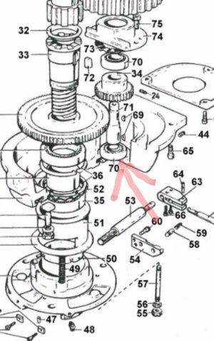
The cheapo gear puller that finally came in has really large claw ends that can't reach under things. I'm going to Princess Auto end week to pick up another cheap puller that will hopefully let me get the bearings off the vari disc assemblies.

Beware of cheap pullers. Jaws break, threads strip, arms bend. In my mind, a really good puller is a great investment. After many disappointments, I finally broke down and bought a really good one. It is a combo 180 (two arms) and 120 (three arms) that has not failed me (yet). I've used it to pull/push huge 2" pins on farm equipment and on my backhoe. Just sayin, buy a good one and only cry once.

Further to the use of pullers - sometimes I find that the Jaws will not grab even if they do fit. When this happens, I wrap fence wire around them (acting like barrel bands) to hold them in place before I put any significant torque on the puller tensioner. That is in fact what I had to do to get the pulley off of my Hartford Mill. The pulley grooves acted like ramps and the Jaws kept slipping.

You can use almost anything. Even rope should work. I just happen to have lots of fence wire.
 
On my 935 there is this setscrew that engages the nose cap threads. That just rubs me the wrong way on many levels but I put mine in lightly with a drop of blue Loktite.

On my Bridgeport and my Hartford, there is a drilled recess in the threads so the set screw does not touch the threads.

That means that you have to be careful to align the cap and the quill so the set screw actually engages the recess and not the threads, but it's a piece of cake to do. You could simply add the recess. So the lock tight and the careful light torque are not needed.

My Hartford also has a groove in the end of the quill so that the two R8 set screws are more easily accessed. I plan to add the groove to my Bridgeport too.

20210706_112613.jpg


As I stated earlier, the groove could become a dirt trap which could get into the threads. However, it would be easy to make something to fit it or even to stuff it with some Kleenex. It's an awesome convenience and worth some effort. I plan to make a groove like that on my Bridgeport too.
 
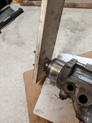
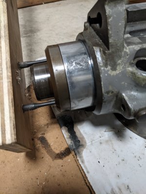
Inspired by @PeterT I did a quick/rough/awful version with some plywood. I have to keep one fit on the housing while I pull on the plywood. It would only move 10 degrees at a time. Manged to get it a 1/4 turn and started to slowly see a crack. I sprayed some WD40 in there and it's dripping out all dirty. I also notice after turning the nose that the spinning the spindle sleeve seems more rough, and making some scrapping noise. Not sure if it's the bearings or what? Hope I'm not ruining anything ... :oops:

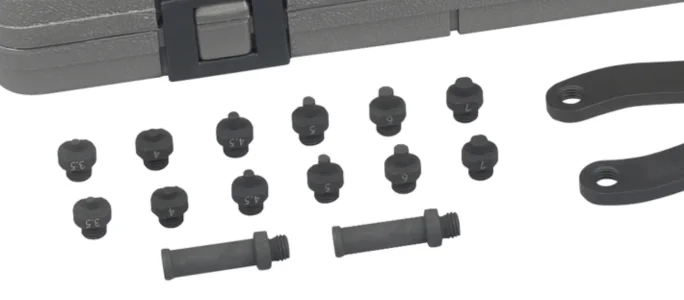
My wood isn't drilled precisely so the taps are skewing and burring the edge of the opening. So I think I will order some pin spanners. Any recommendations? I bought this one but realized the head is way too big:

1625786716643.webp


PXL_20210708_223409300.jpg


PXL_20210708_230757817.jpg
 
Any recommendations? I bought this one but realized the head is way too big:

I got the exact same one on Amazon. Pure junk. Arms are too fat and one was cocked sideways at 20 degrees or so. It was already in return mail when I read your note. I prolly won't buy another. I like the wooden design and if it ever fails me, I'll make my own steel version specific for the job. I did like the principle of the junk version though with a hinge and threaded in Pins so I may copy that design, but fix the quality.

Didn't have your experience with either mill. Both came off easily once I removed the set pin. Getting them back on seems to be the hard part!

I wouldn't worry about buggering up the holes a bit. If you wanna see a mess, look at the photo I posted of the nose on my Hartford. You will also notice that the previous owner just drilled new holes 90 degrees from the old ones and spaced them out away from the spindle at the same time. I'll do that on my Bridgeport too.

I doubt you hurt anything but beats me why that happened. Some dirt in there?
 
Inspired by @PeterT I did a quick/rough/awful version with some plywood. I have to keep one fit on the housing while I pull on the plywood. It would only move 10 degrees at a time.

I think your pins are simply too long. Cut a hole in the wood so it slips over the nose. That should stiffen it up.
 
@Susquatch yup I looked at the spanner for 5min after realizing it didn't fit and put it right back in the Amazon mailing box lol. It's going back this weekend.

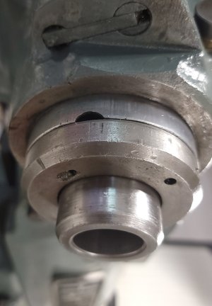
Yeah I remove the set screw no problem but the nose is just really, really stuck. I don't intend to take apart the spindle. I just want to take the nose cap to clean it up and figure out where the groove is to properly line up the set screw again.

Yeah, I may just take my jig saw and rough out a hole to fit the spindle nose in. I'll drill smaller holes so the end of my pin punch fits snug.

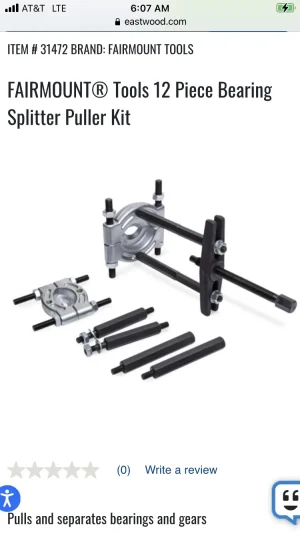
Did you remove bearing from your vari-disc assembly yet? I tried a bunch of Princess Auto pullers and none of them can are shaped well enough to grab. I'm really tempted to just splurge and get the Posi Lock pullers like that guide suggested, but can't tell if I need a 4" or 6" model...
 
Don't laugh at Mr. Woody, it worked haha. I had read where guys were having to grind the pin ends of those expanding spanner type wrenches to engage properly but this might be a function of the wrench model and/or 935 mill. Yes 2 set screws used for the collet guide, dog point & retention. The reason I was in there to begin with. You don't want it protruding too far in or it can jam up in the R8 slot.

Do you have dimensions of the the pin holes and spindle circle? I will attempt my own quick version of this.
 
@Susquatch Yeah I remove the set screw no problem but the nose is just really, really stuck. I don't intend to take apart the spindle. I just want to take the nose cap to clean it up and figure out where the groove is to properly line up the set screw again.

Yeah, I may just take my jig saw and rough out a hole to fit the spindle nose in. I'll drill smaller holes so the end of my pin punch fits snug.

Did you remove bearing from your vari-disc assembly yet? I tried a bunch of Princess Auto pullers and none of them can are shaped well enough to grab. I'm really tempted to just splurge and get the Posi Lock pullers like that guide suggested, but can't tell if I need a 4" or 6" model...

At first, I marked my nose with a sharpie and then after I accidentally rubbed off the sharpie, I marked my nose with a punch so I'll always know where the set screw belongs. I did the same thing with all my lathe chucks. Basically I install them in each lug position until I find the one with the least runout on the chuck itself. Then I mark it so it always goes in the same place.

If you don't have big Forstner bits, try putting a boring bit into your drill press or even a hand drill instead. Makes a much cleaner hole than a jig saw. Although it prolly doesn't matter..... Lol!

Funny, no I have not pulled any bearings on anything yet. I don't plan to until I can figure out how to pull them easily! We are in sync once again!

I dont like the idea of drilling the case. And like you, I have not found a suitable puller. So right now, I'm thinking I might have to make something. I'm thinking about making a shouldered sleeve on my lathe that will go into the bearing but stops at the shoulder. Then inside threading it for my slide hammer, then splitting it in half. You stick the two halves into the bearing so the shoulder is on the other side, then screw in the threaded rod of the slide hammer. The rod holds the halves tight against the bearing. A few whacks and it should come out. I can make collars to fit any bearing as long as they are open on the other side to take the shoulder.
 
Here you go. Handle is shortened to fit on paper. And no guarantee whatever spacing they used on a 935 matches a real BP. I thought maybe pin circle was 58mm but often times these machines are a mashup of imperial & metric dimensions. Or maybe the circle is 58mm and they missed by a little in which case, trust the physical measurement. Anyways I just printed this, glued it on the ply using manual mode center punch to insert close fitting pins & it worked out. Another good reason for wood is you don't feel so bad if it doesn't work out on first try. Good luck
 

Attachments

I'm really tempted to just splurge and get the Posi Lock pullers like that guide suggested, but can't tell if I need a 4" or 6" model...

Wow! Those ARE expensive! I don't think I'll be doing that.

I'm also not convinced the bearings have a lip that can be grabbed with one of those or that the leadscrew won't damage the housing.

Anyway, the principle is similar to what I was thinking - just I was going to grab the bearing from the backside with a little collar.

Just, I'm not sure there is enough space back there or that I wouldn't damage the wave washer.

So, how about the same idea but with no collar so that the threaded sleeve tightens against the inside of the bearing instead? Think of it a bit like a pipe stretcher/expander. Except there is no way the bearing can be expanded so it will just get tight. My guess is that it won't take much.
 
Last edited:
At first, I marked my nose with a sharpie and then after I accidentally rubbed off the sharpie, I marked my nose with a punch so I'll always know where the set screw belongs. I did the same thing with all my lathe chucks. Basically I install them in each lug position until I find the one with the least runout on the chuck itself. Then I mark it so it always goes in the same place.

If you don't have big Forstner bits, try putting a boring bit into your drill press or even a hand drill instead. Makes a much cleaner hole than a jig saw. Although it prolly doesn't matter..... Lol!

Funny, no I have not pulled any bearings on anything yet. I don't plan to until I can figure out how to pull them easily! We are in sync once again!

I dont like the idea of drilling the case. And like you, I have not found a suitable puller. So right now, I'm thinking I might have to make something. I'm thinking about making a shouldered sleeve on my lathe that will go into the bearing but stops at the shoulder. Then inside threading it for my slide hammer, then splitting it in half. You stick the two halves into the bearing so the shoulder is on the other side, then screw in the threaded rod of the slide hammer. The rod holds the halves tight against the bearing. A few whacks and it should come out. I can make collars to fit any bearing as long as they are open on the other side to take the shoulder.
Can you post a picture or point me to a post with the picture of what you’re trying to pull?
 
@architect , you could also drill a hole 1/2 way between the pin holes for a 3/4” wooden or aluminum dowel. Draw it up in a 3/4” collet. It will greatly stabilize your tool and will force the wooden handle to rotate about the spindle axis - which is the same center of rotation for the ring.

The ring is probably tight because the threads are a bit mashed as someone prior to you forgot to remove the second set screw…
 
@architect , The ring is probably tight because the threads are a bit mashed as someone prior to you forgot to remove the second set screw…

I thought there was only one sscrew in this case. But it does seem that two screws are used here and there randomly.

After thinking about it some more, my guess is that someone tightened the set screw on the threads instead of aligning the screw with the corresponding screw relief first. That would mash up the threads too.
 
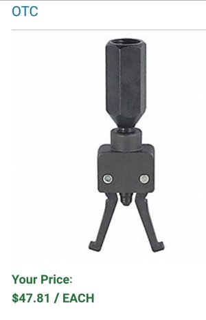
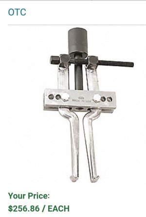
Here are some bearing pullers available at Grainger.

Screenshot_20210709-083549_Chrome.jpg


Screenshot_20210709-083438_Chrome.jpg


Both are sort of like what I had come up with in the dark recesses of my mind, except mine would be a custom fit to a given bearing. And mine would be hundreds if times stronger because there are no arms to bend or deform.

All require that the bearing not sit flush in its recess such that the "hooks" can grab the back of the bearing.

I'm gunna wait until I have a replacement bearing in my hands that I can lay an eyeball on before I decide exactly what to try first.

The nice thing about my idea is that you can always cut the back collar off and use a couple of shims to create a compression fit instead. But I'm pretty confident that it will work especially after I saw these and had a good look at the way that those Posi-Lock pullers work.
 
Back
Top