• Spring 2024 meetup in Calgary - date Saturday, April 20/2024. discussion Please RSVP Here to confirm and get your invitation and the location details. RSVP NOW so organizers can plan to get sufficient food etc. One week to go! More info and agenda
  • We are having email/registration problems again. Diagnosis is underway. New users sorry if you are having trouble getting registered. We are exploring different options to get registered. Contact the forum via another member or on facebook if you're stuck. Update -> we think it is fixed. Let us know if not.
  • Spring meet up in Ontario, April 6/2024. NEW LOCATION See Post #31 Discussion AND THE NEW LOCATION

Bridgeport Project

historicalarms

Ultra Member
You mentioned this before.

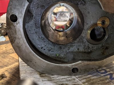
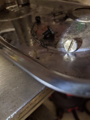
My nose cap DOES NOT HAVE a set screw AGAINST THE THREADS. The set screw has a particular spot on the nose cap threads that it is designed to fit into. It is a recessed pocket in the threads of the quill. Here is a photo.

View attachment 16040

For now, I have a sharpie mark on the nose cap so I know where the recess is so I can align it with the set screw on the quill. I will put a punch mark there after I decide which mill to keep.

I totally agree with your concern though. It bothers the daylights out of me to tighten any lock screw against any threads too. And no offense intended, but I don't like the lead ball approach either.

Any time I have ever encountered that, I have tried to design something to do the same thing without the screw mashing against threads. I've been doing this with my stuff for over 40 years. Ever since the first time I got seriously bitten by this design flaw. And that's what I call it - a design flaw. Set screws should NEVER engage in the threads of anything!

My favorite method is to use split rings where I can. These are basically a regular lock ring with a split in it. The split is then drilled side-to-side and then tapped for a small Allen screw which draws the split together tightening the lock ring in place.

Here is an example. The original lock ring on the right and the replacement on the left.

View attachment 16042

Of course you can't really do that with the nose cap. But I'm fine with the recessed pocket for the set screw.

Ahh yes the old RCBS loading die rings. My first experience with buckshot between the grub screw & threads, Actually I have die sets from the early 60's that me old man used and he was ham handed as anybody with a wrench of any kind....If it was tight another 1/2 turn wouldn't hurt...The treads on those dies are still like new.
There is a couple of bugaboo to those split rings, they work excellent on any single stage C-press where access is free but one any rotary press with a tool head where space is at a premium those damn dies always adjust to where the ring grub screw is inaccessible LOL. And also the hexagon locking rings some die makers use, would not work well being split-ring.

All-in-all I would still consider the lead buckshot a viable solution to any grub screw-thread engagement.
 

PeterT

Ultra Member
Premium Member
At the end you will see Barry hammer the end nut back on with a spanner and a decent size dead blow hammer. The quill housing is held in copper jaws in a sizeable vice.
When he hammers that nut on it is going to be pretty secure and will give you an idea of how tight it might be.

That's the vid I recall watching. At ~14:00 he shows the nose cap going on, first hand tighten with the short spanner & then (paraphrasing) 'that's about all you need... but if you want to go a bit more...'. he breaks out the big ass dead blow but it looks more like a love tap on the pin wrench. Now what happens between this installation & years later come removal time loosening those threads is another matter. Corrosion Glue maybe?

And his preference is just grind the set screw short, no new counterbore landing area drilled, no antiseize on the threads, no squashable medium in the hole, no brass set screw, just a dot of Locktite & very light set screw contact. Guess there are many ways to skin the cat.
 
Last edited:

Susquatch

Ultra Member
Administrator
Moderator
Premium Member
I have watched all of the H&W videos that apply to my two mills.

I agree that they are excellent.

However, they don't cover every possible scenario, nor would I expect them to.

For example regarding the subject at hand, the pesky nose cap. Yes, he shows how he does it - even to the point of using love taps with a sledge hammer. But what if we don't have that kind of spanner? What if our vice isn't big enough?
What if......

Another example is getting that bottom bearing out. He tells you how he does it but never actually shows you. And frankly, I have no desire to drill holes to punch my bearing out. He also mentions a special tool he uses and sells. But darned if I could find it!

Anyway, I'm sure you guys get the drift. The wonderful thing about this forum is the experience and wisdom of its members. Where the videos have a gap, there is a member who has been there or done that or with great ideas.

I'll make my own puller if the Hydraulic Grease trick doesn't work. Both approaches are better than drilling holes for a punch. I don't know about H&Ws secret tool.

I'll also make my own nose removal tool. It will work better than any spanner ever could.

I've ordered a bunch of parts from H&W. And like many others, I'm grateful to Barry at H&W for his excellent videos. But I'm especially grateful to all the awesome members of this forum who have gone out of their way to explain things and offer their suggestions and advice
 
Last edited:
Forums like this one are pure gold man.
I have watched all of the H&W videos that apply to my two mills.

I agree that they are excellent.

However, they don't cover every possible scenario, now would I expect them to.

For example regarding the subject at hand, the pesky nose cap. Yes, he shows how he does it - even to the point of using love taps with a sledge hammer. But what if we don't have that kind of spanner? What if our vice isn't big enough?
What if......

Another example is getting that bottom bearing out. He tells you how he does it but never actually shows you. And frankly, I have no desire to drill holes to punch my bearing out. He also mentions a special tool he uses and sells. But darned if I could find it!

Anyway, I'm sure you guys get the drift. The wonderful thing about this forum is the experience and wisdom of its members. Where the videos have a gap, there is a member who has been there or done that or with great ideas.

I'll make my own puller if the Hydraulic Grease trick doesn't work. Both approaches are better than drilling holes for a punch. I don't know about H&Ws secret tool.

I'll also make my own nose removal tool. It will work better than any spanner ever could.

I've ordered a bunch of parts from H&W. And like many others, I'm grateful to Barry at H&W for his excellent videos. But I'm especially grateful to all the awesome members of this forum who have gone out of their way to explain things and offer their suggestions and advice

Die grinder with a carbide burr and some very careful grinding? I've removed stubborn bearings this way in the past. Its definitely tricky.
 
Just a general followup on @architect 's post of needing a new motor.

D&W has one of their motor rebuilding videos where barry says he's going to replace a stator in a 575v or 600v motor with a 240 one and make the motor a 240.

I'll try and find the clip to confirm, but is this possible? ie: replace the 575v/600v stator in a bridgeport field to get a 240v 3ph motor?
 

Dabbler

ersatz engineer
but is this possible?

It can be done. There used to be a shop in Ft McMurray that did it for 200$. That was 30 years ago.
 
but is this possible?

It can be done. There used to be a shop in Ft McMurray that did it for 200$. That was 30 years ago.

Barry at D&W seems to imply it was just a stator swap into an existing field. I'm not talking about a rewind. I gotta find the video link.
 

Proxule

Ultra Member
Kinda late to the party here but thought I'd show a couple pictures of a tool I made to get my spindle nose off - maybe it'll help someone next time. Just a little different pin wrench - gotta make it before you take the mill apart (or on your spare mill). Thick enough to get a big pipe wrench on. SHCScrews spaced appropriately and turned down to correct dia. Trap the tool between the quill nose and your vise or the table - insert a couple business cards under so you don't scar vise or table. Remove horizontal set screw as well as the grub screw. Mine was right hand thread (chinese clone) others could be left so don't get too angry with it too soon. Now you've got something trapped in there that won't slip and you can really get some force on it without damaging anything. Save it for next time ! View attachment 16068View attachment 16069

Very slick, thanks
 

Susquatch

Ultra Member
Administrator
Moderator
Premium Member
Kinda late to the party here but thought I'd show a couple pictures of a tool I made to get my spindle nose off - maybe it'll help someone next time.

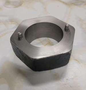
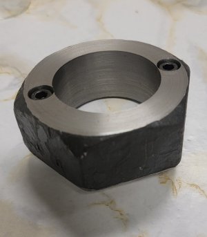
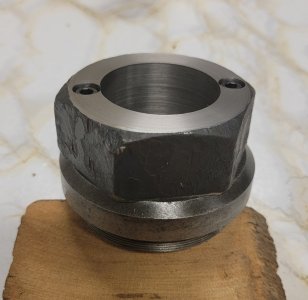
Same principal as my bored out nut except you intend it to be used with a pipe wrench and I intend to use mine with a socket or open end wrench.

Finished my version of the nose cap removal tool inspired by @architect. Cap came off like butter off a knife. Very happy.

Easy to use with a open end wrench or a decent size monkey wrench. As a farmer, I also have sockets that big.

20210715_201728.jpg

20210715_201744.jpg

20210715_202101.jpg

I say finished, but when I'm done all my priority work, I'll clean up the nut by facing off all the sides and bevel the end so it looks as pretty as it works.
 

Susquatch

Ultra Member
Administrator
Moderator
Premium Member
Die grinder with a carbide burr and some very careful grinding? I've removed stubborn bearings this way in the past. Its definitely tricky.

Ya, I removed a disk gang cushion block bearing that way once too. It was downright scary. Ended up torching, grinding, and beating on it before I was finally able to get the outer race out. That particular set of disks is worth 80K new. I was a basket case.
 

architect

Super User
So I'm trying to get the quill assembly back into the housing but it seems to be really stuck, and caught on the skirt. Any thoughts how to make this work? Everyone's videos seem to make it easy and just require few skirts of WD 40.

PXL_20210718_153005297.jpg
PXL_20210718_152953038.jpg

I didn't remove the top screws holding down the filter before sliding the skirt out. Not sure if that may have caused any issues. The screws appeared to been filed down to provide clearance. Is this factory or did the previous owner do this themselves?

PXL_20210718_153051816.jpg
 

RobinHood

Ultra Member
Premium Member
Did you check for burrs on both the quill cartridge and the housing bore? Remove any and all of them.

These parts are very close tolerance and will bind if the alignment is off even the slightest. You need to be very gentle to get the quill started co-axially in the bore. Use a light hand tap to align. It is easy to over-shoot center and end up stuck on the other side. In this video, he shows how he lightly hand taps the quill to get it started. If you could mount the head to something solid, it would help a lot.


I would remove the felt and only put it in after the skirt. He does mention that you could get things hung up on it.

The skirt goes in after the quill is installed.
 

Susquatch

Ultra Member
Administrator
Moderator
Premium Member
Grease didn't work on my bottom bearing. Just squirted up through the cage and dust shield like they were not even there.

Custom pullers R Us will be at it again soon.

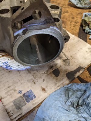
Looks like I only have a few thou clearance at the bottom of the bearing. Can't figure a way to measure it. So it will have to be trial and error.

Also thinking ahead, seems like an expanding collet type system is probably best, but how to control the expansion at the same time as controlling the grip will be a challenge. Not sure a copper or brass shim would be strong enough.
 

Chicken lights

Forum Pony Express Driver
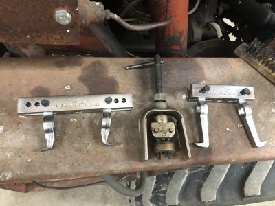
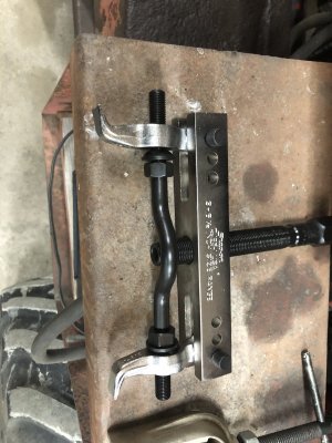
9BEFB591-6A43-4691-9DC1-D198A48D83F8.jpeg 71B6B2AD-2611-43B7-9CE4-2CB2FCEE2522.jpeg 1590F7BA-E257-4226-AF46-0A6BA3547269.jpeg Any of those work for you? Or give you any ideas? The middle one in the first pic, as you screw down with the top handle, shoves the jaws further apart. Then you use a wrench on the nut to pull the bushing/bearing out
 

Susquatch

Ultra Member
Administrator
Moderator
Premium Member
View attachment 16148View attachment 16149View attachment 16150Any of those work for you? Or give you any ideas? The middle one in the first pic, as you screw down with the top handle, shoves the jaws further apart. Then you use a wrench on the nut to pull the bushing/bearing out

All somewhat similar to what I planned to try and make. But they are all way too big. The center of the bearing is only 0.698".

I don't have a drawing yet but basically, I planned to make an expanding collet - just one split or maybe four. (I HATE SPLITTING.) The main collet body would be 0.7 OD but there would be a tiny "claw" at the very end (maybe 0.74) that would grab the bearing from the back. There is virtually no room behind the bearing for anything substantial. You push the collet through and it "snaps" into place. The inside of the collet is threaded to take the 5/8-18 of the threaded rod on my slide hammer. Since I will be making the collet, I will prolly make the inside thread a tight fit so the threaded rod acts to expand the collet for a VERY tight fit to hold the rear hook in place. Ideally, I'd like to incorporate some kind of expansion system to force a friction fit of the entire collet if the hook doesn't work. I just don't know how to do that just yet. I'm guessing it will take me a few days to make it. But my parts are not here yet from H&W so I have some time.
 

RobinHood

Ultra Member
Premium Member
Grease didn't work on my bottom bearing. Just squirted up through the cage and dust shield like they were not even there.

Try using wet toilet paper instead of grease (soak in oil). I did not realize it was an open bearing on both sides - grease would have a tendency to squirt right through.
 
Top