Looks like
@Aburg Rapid Prototype has some industrial strength software at his disposal, but I will offer a few points FWIW.
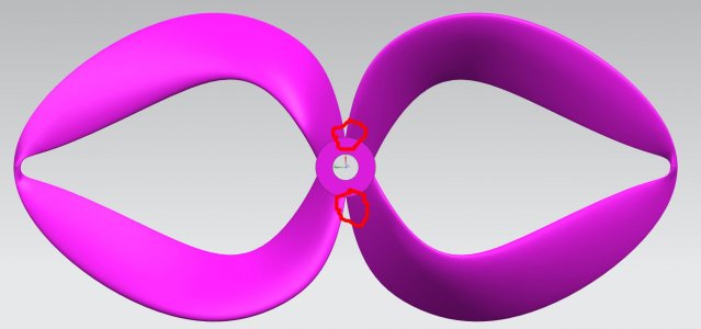
- where & how you terminate/transition your airfoil relative to the hub will likely have zilch implications on performance. Its all messy 'extra' turbulent flow for a number reasons outside the scope. So I recommend you use that fact to your advantage & make the mold makers job as pain free as possible in terms of parting line & parting plane.
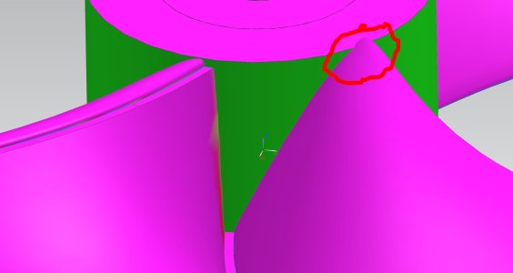
- your airfoil nose likely has a 0,0 type coordinate. I would alter the hub so that that point occurs on the circular bub and not coincident with the fillet or any other feature that makes it a 3-way. ie. most likely the mold must part on the airfoil chord line & not be adversely affected by this other geometry
- its very rare for any kind of prop to not have a fillet in a transition like this hub. Its usually always 'better' aerodynamically/hydrodynamically but you may also run into other issues. Its the most stressed area of the entire prop, exactly where you don't want a corner. It will likely create issues with any kind of molding whether injecting plastic, reinforced resin, layups... All it takes is a void & bye-bye blade. Now with a fillet, that may or may not play nice with parting issues, that has to be re-examined.
View attachment 31901
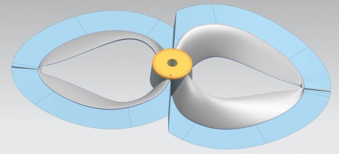
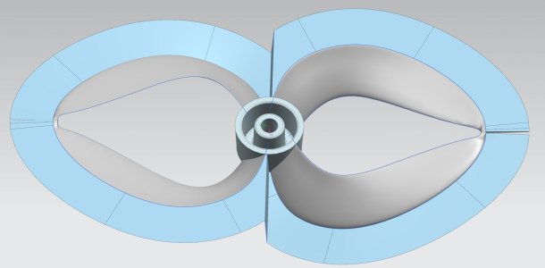
Another thing I forgot to mention, might be a tight squeeze, but if your single part molds become a real bear, you might be able to solve some issues with these keyed type blade principles. That way your blade is one mold & the hub is another. Obviously some other big picture pros & cons, but just throw-in it over the fence. For bonus points you could have retracting folder haha
View attachment 31903