• Spring 2024 meetup in Calgary - tentative date Saturday, April 20/2024. Other regions are also discussing meet ups. If you want one in your area get going on organizing it! discussion
  • We are having email/registration problems again. Diagnosis is underway. New users sorry if you are having trouble getting registered. We are exploring different options to get registered. Contact the forum via another member or on facebook if you're stuck. Update -> we think it is fixed. Let us know if not.
  • Spring meet up in Ontario, April 6/2024. NEW LOCATION See Post #31 Discussion NEW LOCATION

Still learning new things in fusion 360 regularly...

TorontoBuilder

Ultra Member
Nice CAD work. That is a pretty mind bending shape.

Molds looks very challenging, likely varying parting plane surfaces & probably sub structure elements. I've seen some 3DP promotional videos where guys are direct printing casting ready wax material, thus leaving only the trivial task of investment & casting haha (that's a joke, I don't even qualify as bystander status). But maybe you can go straight from CAD file to 3DP nickel or bronze, no middle man. I'm guessing their shrinkage & other dimensional issues might be a factor to contend with, but I mean fluid dynamics is complex sh*t. The chances of getting the first iteration 100% right is probably zero even if it were cast perfect. Attached an old Tom Lipton video where he outsourced the handle & did some post finishing. Check the vid but I seem to recall ~75 USD but those prices are probably outdated & not sure if name drop discount although that's not his style. Anyways, easy to upload a file & get a quote. I would think since that time even more services avilable & better quality.

View attachment 30938


Yeah there are some wax filaments to directly make parts. The resolution is not nearly as good as sla printing and then making a mould though.

I've looked into direct to metal casting with post print sintering, it is an option with bronze for sure.... so boat props will be much easier if I wanted to pay more
 

TorontoBuilder

Ultra Member
You got me there. I've only seen them from the sidelines. You want to put in 'R' & back into the hangar do you LOL?
This one is for electric outrunner style, 26" prop, maybe scalable?

Maybe.

I follow Christian and he also has a variable pitch contra-rotating model that I was thinking of trying to replicate some time.


PeterT

Ultra Member
Premium Member
Another thought. If your mold could be segregated so the end bit was attached obliquely, that leaves the main mold as pretty conventional & represents 95% of the total prop. I'm doubtful the end has much in the way of an airfoil, probably more of a 'joiner-upper' for the blades? In which case you can fudge the section properties so that a separate tip mold could part correctly. Still a headache, but slightly less headache.

With CF the question becomes, how are you building it? In my world only the outer skin layer(s) are spread tow like Textreme, or cloth, but the inner are typically uni (tow) fibers to take the load. That's why they have these 'nail board' jigs to get all the progressive fiber lengths. Now these props are very thin section & large diameter spans which is the worst combination for strength. I've also seen a technique where they cut a specific series of layers like prepreg, again engineered to give the section or fill properties. Maybe if the section is sufficiently thick it works to advantage where random fiber slurry core is feasible. Either way its tricky to get the right fill, close the mold so that there is slight compaction but no voids & minimal flashing. But hey, others have done it, so can you.

Here is a link to props I run, shows some of his molds down the page


Attachments

  • SNAG-2023-02-20 11.05.27 AM.jpg
    SNAG-2023-02-20 11.05.27 AM.jpg
    72.9 KB · Views: 4
  • EDT-2023-02-20 10.57.01 AM.jpg
    EDT-2023-02-20 10.57.01 AM.jpg
    19.1 KB · Views: 4

TorontoBuilder

Ultra Member
Another thought. If your mold could be segregated so the end bit was attached obliquely, that leaves the main mold as pretty conventional & represents 95% of the total prop. I'm doubtful the end has much in the way of an airfoil, probably more of a 'joiner-upper' for the blades? In which case you can fudge the section properties so that a separate tip mold could part correctly. Still a headache, but slightly less headache.

With CF the question becomes, how are you building it? In my world only the outer skin layer(s) are spread tow like Textreme, or cloth, but the inner are typically uni (tow) fibers to take the load. That's why they have these 'nail board' jigs to get all the progressive fiber lengths. Now these props are very thin section & large diameter spans which is the worst combination for strength. I've also seen a technique where they cut a specific series of layers like prepreg, again engineered to give the section or fill properties. Maybe if the section is sufficiently thick it works to advantage where random fiber slurry core is feasible. Either way its tricky to get the right fill, close the mold so that there is slight compaction but no voids & minimal flashing. But hey, others have done it, so can you.

Here is a link to props I run, shows some of his molds down the page


moulds will definitely needs to be segmented.
 

TorontoBuilder

Ultra Member
I had some time where I felt well enough to figure out how to model a toroidal propeller. I had done something similar a few years back but forgot the steps needed to create 3D lines that curves on multiple planes. I had to figure out how make a curved surface from one a curve along one plane in order to project a curve on a plane 90 degrees to the first onto the curved plane in order to create rails to constrain the loft of the propeller blades.

The image below illustrates the two complex curves that comprise the upper rails for the two leading edges of the propeller on one side of the prop. The flat plain in light blue has the two 2D curves that form the rails for the trailing edges of the props.
View attachment 30934
The image below is 13 different sketches, showing the same elements as above and the individual profile sketches for the propeller on their 11 different planes from a more tilted angle for better clarity of the base sketch

View attachment 30937

This and the opposite CW prop will be 3D printed so it has a flat on the bottom to attain enough adhesion to the bed. I'll test against a standard 5040 propeller to see if it has better thrust and sound characteristics before doing small production run for further testing.

It will be printed at a very fine setting, then receive post printing heat treatment, sanding and primer and paint coating. Then I'll make a multipart silicone mould in order to make small production runs with different plastics and hard two part urethanes.

View attachment 30932

View attachment 30933

View attachment 30929

I added carbon fiber for a few renderings but 5 inch props are too small for me to make from CF

View attachment 30930

View attachment 30931

Update for anyone trying to learn from my post...

I used 6 profiles per side of each blade. If there is any misalignment of your profiles the parts will be wavy, and if you look at the above in just the right way you can see tiny imperfections.

The solution is to use the bare minimum number of profile sections to create the loft in combination with rails to make the part conform to your desired shape. I initially had issues with my profile placements causing the loft to intersect itself returning errors but with a few changes and fiddling I revised the prop to use just 3 profile sections per side to have perfectly smooth even curves with no undulations.

I do not believe a tri-loop prop will be more efficient but I modeled one to try as well, it reminds me of a trillium flower.

5 inch triloop.PNG


5 inch triloop angled.PNG


Revised Bi-loop

toroidal prop oblique view.PNG


toroidal prop plan view.PNG


toroidal prop end elevation.PNG
 

Matt-Aburg

Ultra Member
Do you want to build and Aluminum Mold? I was reading that you can test flow in Solidworks. They have a free trial available. After you get it close, I can do the DFMS to make it moldable with self releasing parting line.. no mechanisms... I need STEP files to see. If you want to cut me a preliminary design, I can make suggestions ....


TorontoBuilder

Ultra Member
Do you want to build and Aluminum Mold? I was reading that you can test flow in Solidworks. They have a free trial available. After you get it close, I can do the DFMS to make it moldable with self releasing parting line.. no mechanisms... I need STEP files to see. If you want to cut me a preliminary design, I can make suggestions ....

I shall be in touch.

I think I'll muddle through with the thrust test stand and design iterations method. Yeah I'd love an aluminum mould. I'd be able to better refine the foil so I dont need a flat section to start the print on to ensure adhesion to the printing surface
 

TorontoBuilder

Ultra Member
@TorontoBuilder where are you getting your foil sections from? Was this just a mockup model to get the lofting workflow?
(the sections don't look anything like the example you originally referenced).

View attachment 31028View attachment 31029
The example I originally referenced was for a Sharrow boat propeller. It has a different design due to the density differences between the fluids.

For the aircraft propeller I started with a foil shape taken from a standard 5045 propeller design and modified it. The modifications I made wear to allow it to be 3D printed successfully (hopefully anyway, I haven't yet test printed it) and to match as closely as I could the visual look of the final iteration of the MIT propeller prototypes.
 

PeterT

Ultra Member
Premium Member
I figured you were on top of it but just in case. But even same density water prop A to water prop B would likely yield significantly different optimized foil sections if the 2 applications are only slightly different. For example a higher output engine can deliver more torque, therefore could utilize increased pitch or section span or diameter or rpm or.... But that usually means increased section strength (thickness) which often overrides what would be better polars of a thinner section. In air medium, smaller 'model type' props & wings typically have even larger deviations to their FS counterparts primarily because Re is orders of magnitude different, which makes the Cl,Cd,Cm polars very different & this is perpetually varying along the span. Anyways, not sure if you are wanting to go deep nutbar or just make some cool things & have fun.

I'm dating myself but link has some common references & downloadable tools, CAD ready airfoil coordinates etc. XFOIL is a <cough> simpler 2D section simulator by Dr. Mark Drela, been around forever. I think it was part of his thesis project back in the day, graciously donated to public domain. There are better 3D simulation tools like XFLR5. Not sure if applicable to hydrodynamics though. The Solidworks reference looks interesting but have no idea what CFD they use. That stuff used to be either aftermarket plugin based or part of the uppety Pro version. I know of some folks in RC community who do this stuff for a living & have access to all software toys, but I was not getting a warm & fuzzy the sims with CAD packages were very accurate for smallish stuff. Props (very small aspect ratio) I think are even more specialized/different again. Voodoo! Good luck with your journey.


TorontoBuilder

Ultra Member
I figured you were on top of it but just in case. But even same density water prop A to water prop B would likely yield significantly different optimized foil sections if the 2 applications are only slightly different. For example a higher output engine can deliver more torque, therefore could utilize increased pitch or section span or diameter or rpm or.... But that usually means increased section strength (thickness) which often overrides what would be better polars of a thinner section. In air medium, smaller 'model type' props & wings typically have even larger deviations to their FS counterparts primarily because Re is orders of magnitude different, which makes the Cl,Cd,Cm polars very different & this is perpetually varying along the span. Anyways, not sure if you are wanting to go deep nutbar or just make some cool things & have fun.

I'm dating myself but link has some common references & downloadable tools, CAD ready airfoil coordinates etc. XFOIL is a <cough> simpler 2D section simulator by Dr. Mark Drela, been around forever. I think it was part of his thesis project back in the day, graciously donated to public domain. There are better 3D simulation tools like XFLR5. Not sure if applicable to hydrodynamics though. The Solidworks reference looks interesting but have no idea what CFD they use. That stuff used to be either aftermarket plugin based or part of the uppety Pro version. I know of some folks in RC community who do this stuff for a living & have access to all software toys, but I was not getting a warm & fuzzy the sims with CAD packages were very accurate for smallish stuff. Props (very small aspect ratio) I think are even more specialized/different again. Voodoo! Good luck with your journey.


Yeah I have seen xfoil and I even used an old java based propeller evaluation tool from germany years ago, but didn't want to worry too much about the foil sections to start with until I had figured out how to get the damn things lofted properly in fusion. I had to modify the crescent airfoil to be able to 3D print the design to test it, and I am sure that affects the pitch.

The pitch angle on this prop does decrease from the blade root to the tip in order to attempt to maintain a constant pitch BUT the sketches I used for the blade root and tip profiles are not correct to maintain the correct constant pitch. My tip profile gave me all sorts of issues not wanting to loft and follow the rails.

Tweaking the sketches to assure the correct constant pitch is on tap for iteration number two.
 

PeterT

Ultra Member
Premium Member
The pitch angle on this prop does decrease from the blade root to the tip in order to attempt to maintain a constant pitch BUT the sketches I used for the blade root and tip profiles are not correct to maintain the correct constant pitch. My tip profile gave me all sorts of issues not wanting to loft and follow the rails.
Yup, been there done that. And to complicate matters, two different modelers may handle the same geometric constraints differently. There seems to be 101 ways to fail, or even if you get a surface & it passes zebra line sniff test. Convergence issues approaching the the tip can case issues for a number of reasons. Sometimes extra section concentrations help. Sometimes its best to get 95% of the wing good, just terminate & deal with tips as a separate entity. Its a bit of cop out but generally tips don't contribute much of anything in real life unless you have some specific goals/shapes, so its as good a place as any to sweep dust under the carpet. You have super funky tips so I suspect will have to do this anyways.

A way to test conformance aside from zebra stripes & other visual assist tools is loft a unified section only vs a blend of different foils. ie. the foil 2D scales in X&Y only as a function of chord length. Now section the lofted solid at some a known position along span, correct (normalize) chord angle & superimpose the actual airfoil. IOW at the same chord length. You can see any deviation the lofting has imposed on the surface & decide if that's close enough. I would expect the more twisted LE & TE rails, the more its going to have a mind of its own. Now you can play with section density & strike the balance of too little or not enough.
 

TorontoBuilder

Ultra Member
Yup, been there done that. And to complicate matters, two different modelers may handle the same geometric constraints differently. There seems to be 101 ways to fail, or even if you get a surface & it passes zebra line sniff test. Convergence issues approaching the the tip can case issues for a number of reasons. Sometimes extra section concentrations help. Sometimes its best to get 95% of the wing good, just terminate & deal with tips as a separate entity. Its a bit of cop out but generally tips don't contribute much of anything in real life unless you have some specific goals/shapes, so its as good a place as any to sweep dust under the carpet. You have super funky tips so I suspect will have to do this anyways.

A way to test conformance aside from zebra stripes & other visual assist tools is loft a unified section only vs a blend of different foils. ie. the foil 2D scales in X&Y only as a function of chord length. Now section the lofted solid at some a known position along span, correct (normalize) chord angle & superimpose the actual airfoil. IOW at the same chord length. You can see any deviation the lofting has imposed on the surface & decide if that's close enough. I would expect the more twisted LE & TE rails, the more its going to have a mind of its own. Now you can play with section density & strike the balance of too little or not enough.
I have completed most of iteration number 2 and it is looking good so far. I have one tiny edit on a profile sketch to do but otherwise it is lofting with the correct pitch angles throughout the blade.

The hardest part was recalling the math to convert from tan a to degrees so I could redraw the foil sections to the precise pitch angles at the 3 loft stations.

Viewing 1/2 of a loop it looks fairly standard except for the funny looking leading edge.

1677041767166.png

For this purpose I think the isocurve analysis is better for visualization. That and section analysis, to verify that the rails constrained the loft properly to assure that the expected pitch angle was maintained. I found an issue via section analysis when all else looked good..

1677042407729.png
1677041986207.png
 

TorontoBuilder

Ultra Member
Here is the process of how I laid out the propeller airfoil profiles in order to obtain an even pitch angle along the length of the propeller blades.

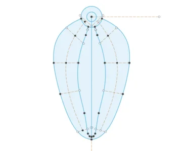
To prep for this I first laid out the primary loop shape on the bottom plane looking down from the top. The highlighted blue lines will be the trailing edges of the blades and the lower rails to guide the loft. The other two edges of the propeller outline need to be projected to 3D planes done in two separate steps.

Most of the dashed construction lines are to align construction planes perpendicular to the bottom plane to perform section analyses to check that the blades lofted correctly, and as planes to sketch the 5 airfoil profiles on.
1677117388490.png

Then I sketched the side view profile.
1677116790492.png
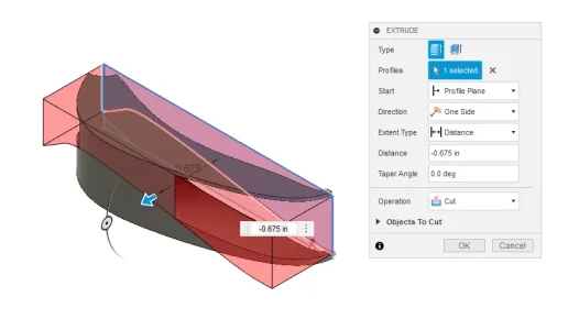
Then I extruded the left lobe of the plan view upwards to create a body...

1677118747306.png

Then I used the upper section of the side view to extrude a cut thru the left lobe body.

1677119157835.png

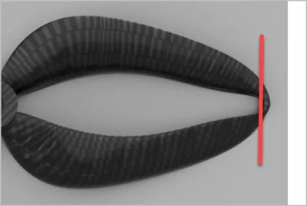
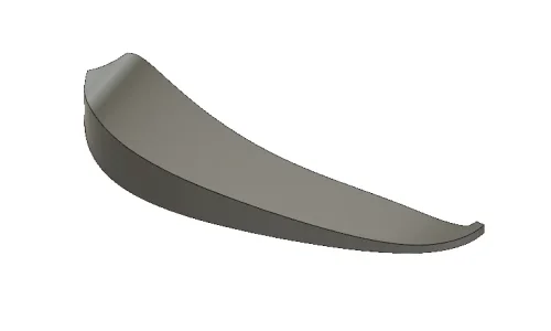
Below is the resulting body. These two extrusion processes were to get the 3 dimensional representation of the leading edge of the left side lobe which will later be projected onto a plane. You can see the curved line highlighted in light blue.
1677117117596.png
You cannot do both lobes at once because the leading and trailing edges are reversed for the right side lobe. The next step is to lay out 3 sketches for the loft, starting with selecting the construction planes, starting a new sketch on the plane, and then projecting lines to where the body intersects each plane.

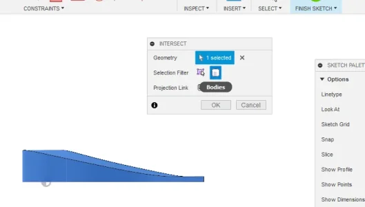
Select the previously constructed plane. Select create sketch.

1677119365549.png
Select create, project/include, intersection. Select the geometry to intersect, in this case the left side body. Make sure the selection filter is on body and not edges. To facilitate the sketching it is best to keep the body set to not visible, and just select if from the left side menu.

1677119862398.png

The selection should look something like as follows, convert all four lines to dashed construction lines, feel free to erase the upper and lower lines if you wish. Place your airfoil sketch inside the construction box being mindful that the profile sketch MUST have a point touching the lower left corner and the upper left corner or the the leading and trailing edge rails will not intersect with the profile sketch making it impossible to loft the blades along the rails. 1677120093010.png
You can see my starting blade root profile where it intersects the hub touches both corners as required. I calculated the required pitch angle for this radius and laid a construction line at that angle to ensure my airfoil closely aligned with the pitch angle. I sketched a base line the width of 2 extruded walls from a 0.4mm nozzle as a printing base. Then I sketched an ideal airfoil using a construction line and then sketched an adjusted airfloil in a solid spline starting at the lower left base corner and ending at the right side of the base line. I then adjusted the spline to match the ideal airfoil as closely as I could.

1677115848781.png
Then I repeated the process for the end airfoil using the same methodology as above. The result looks like this: 1677115548808.png

Then I created a blade tip profile that is common for both left and right portions of the bi-loop propeller. I deleted all the intersection lines but the four spline points are located at each corner of the intersection.
1677122014167.png
Next up are the right side profiles. But if you use the same method you will get this as your intersection result:
1677125338693.png

The leading edge and the trailing edges are reversed... if you were to copy and then mirror the profile from the other side the leading edge will not intersect the projected rail you will make next.

1677125669848.png

Modifications are required to draw a new side profile to use for the right side. I'll cover that in a new post later.
 

Attachments

  • 1677120042881.png
    1677120042881.png
    24.2 KB · Views: 1
  • 1677117030644.png
    1677117030644.png
    24.1 KB · Views: 1
  • 1677116318696.png
    1677116318696.png
    63.8 KB · Views: 1
  • 1677118831281.png
    1677118831281.png
    67.6 KB · Views: 1
This technology popped up in some commercial/military publications several years ago and recently hit general public publications and is making its way into the commercial market.

While it falls under I must understand this category, I have to much on my plate other than to follow it in passing as it crosses my information feed.

My understanding is greatly increased efficiency in part of "winglets" and vented/controlled lift surfaces, with a lot less required HP. As this develops its going to change a lot of things in all industries that require liquid/gas movements of any kind.

Shows the importance of mainstream 3D modelling, simulation and manufacturing. The importance comes from the un-intentional collaboration/development between professional and amateurs alike making leaps and bounds in development.

Well done, looking forward to see what you find.
 

Dan Dubeau

Ultra Member
That's pretty cool. I wonder how much benefit it would be on something like a trolling motor. One might not think it, but that's a HUGE potential market for small performance gains. With a lot of money to throw around at something like this.

Don't know how the closed nature of it would fare in the weeds, but any increase in efficiency directly translates to battery life and performance, and with trolling motors playing such a huge part in tournament fishing there's no doubt you could sell a boatload of them. No doubt in my mind that it's a million (multi) dollar idea.

A resin printer would be a good way to test it out. Even to make a part to take a silicone mold from so you can pour stronger resin parts to test.
 

Susquatch

Ultra Member
Administrator
Moderator
Premium Member
My eye wants fillets adjacent to the hub

Me too!!! I wanted to say this earlier but swallowed the comment because I felt so totally unqualified to say squatt. Better to just keep my mouth shut.

But ya, I think the fillets are required to smooth the flow over the shaft and blades to avoid stagnant pockets at the intersection as well as to maintain a good stress distribution in the structure itself. This was partly behind my earlier question about flow modelling.

Anyways, you guys both rock and the rest of us are jealous. Well, I am anyway.
 

TorontoBuilder

Ultra Member
That's pretty cool. I wonder how much benefit it would be on something like a trolling motor. One might not think it, but that's a HUGE potential market for small performance gains. With a lot of money to throw around at something like this.

Don't know how the closed nature of it would fare in the weeds, but any increase in efficiency directly translates to battery life and performance, and with trolling motors playing such a huge part in tournament fishing there's no doubt you could sell a boatload of them. No doubt in my mind that it's a million (multi) dollar idea.

A resin printer would be a good way to test it out. Even to make a part to take a silicone mold from so you can pour stronger resin parts to test.
Dan you are 100% correct about the efficiency and battery life gains to be had. Trolling motors are ubiquitous on NA waters, so the market would be huge. I had the same thought the first time I saw a sharrow propeller. Sadly the company is targeting the luxury and high end commercial fishing operations and therefore not likely to license anyone to sell props for trolling motors. So it will likely be DIY affair for anyone who wants one and every remix will likely be different making it difficult to see which is best to download and use via thingiverse.

I have plans to make one this year to use in a pod to power my stand up paddle board. It will be like the bixpy that mounts in a SUP fin box. Then I'll just sit in a kayak seat on the SUP when I am lazy and just want to cover ground on the grand river or such and enjoy the view with my camera.

If that goes well then I had been looking at a trolling motor with counter rotating propellers that would benefit from sharrow style propellers. I found that one inventor with more motivation than myself patented a contra-rotating design for a trolling, it is a complex design with both an armature/rotor and a stator/field magnets that rotate in opposite directions during operation. Power transmission is accomplished via slip rings IIRC. The design also drops any pretense of having a rudder, which I find objectionable but it should get the job done. I hate the look of it as well. I've never seen this commercialized at any point since it's patent issuance circa 2012 so I guess it is costly to manufacture, ugly and did not provide sufficient improvement to compete with cheap trolling motors. On a larger scale there are bow thrusters with this arrangement but they are powered like an outboard motor with the engine above, and a shaft turning beveled gears below and I suppose a planetary gear or such

1677173126876.png


1677173179485.png

I'm going another route, I'll make two axial flux direct drive brushless motors with a low KVA rating, in a waterproof housing with no gearing. I've already designed a larger motor in this style for an ebike so I know the process. Each motor will have a stationary center ring that holds the stator and a rotor on either side connected to shaft that passes through bearings mounted concentrically in the center of the stator ring. Below is one half of the rotor assembly:

1677174342663.png

Below is one complete motor in whcih you can see how the central stator assembly can be modified many ways in order to mount the motor to a frame. In this case projections have been added to mount to brackets that will be welded to the bike frame in 3 places. In this case the central shaft is hollow and the same dimensions as a crank set that will pass thru the motor in order to be used as pure pedelec and to provide the perfect chainline as required for gates belt drive.

1677174490296.png


The shaft of the innermost motor will pass through the shaft of rearmost motor. The two stators will fasten directly to the inside of the housing to affect cooling, the The following image is for demonstration purposes only, just to show the layout. So both propellers will be very close together, an efficiency advantage over the previously mentioned motor with the large spacing between the inline props.
03cd05288be88d049b67c9d96c2f1090.png


I do not like the propeller shapes below, but the arrangement will maximize the efficiency of the motor and contrarotating propellers. I am super keen to see if a sharrow design will improve things further.

cb85e07b772a8cd195d022e8351bd52f6260a394.jpeg


For the controls I plan to repurpose a drone flight controller and 4 in 1 electronic speed controller to operate the the dual motors via either a really cheap R/C radio set or an arduino programmed to output S. Bus signals from an analogue input & potentiometer built into a hand control. Having a bunch of radios already I'm leaning towards a radio to start


INTERESTING NOTE:

The inventor (Randall J Wishart) of the ugly contrarotating trolling motor is a prolific inventor and does have some good ideas along with a ton of ambition. He just recently patented high speed slip rings for power transmission and a contrarotating motor design with an optimized mounting system for drone applications.

The company is called CR Flight.. maybe I mentioned them already .They claim the following:

30 - 50% greater thrust efficiency​

Up to 100% increased operating range​

Runs quieter, lower noise​

They do not claim but this but drones equipped with their tech should have superior initial stability and should handle much better especially in windy conditions since each motor set will be close to zero torque, versus that standard technique of having opposing motors that rotate in opposition to each other. The motor torque set way out from the center of rotation on a lever require the flight controller to fight to maintain offsetting torques in order to maintain stability. Sadly, I can't find all the patent documents yet to try to copy this.

motor-propassembly.png
 
Last edited:
Top