Hi - We're having intermittent forum issues. Posts, alerts, and anything involving email like signing up or password changes are having problems but not for everyone or everywhere. Josh is working on it. No ETA right now. Thanks Josh - BTW this is a volunteer forum so SLA's are just best effort.
EDIT -> I manually batch updated about 25 people stuck on the email notification. Try logging in now with your password.
EDIT -> May 8/23. I updated another bunch of users stuck on email notifications. Try to login if you are stuck.
If you really can't get in contact us on facebook or if you know a forum member get them to ask us.
Lofting is something I learned long ago but dont often use outside of rendering previews of fuselages and hulls for models I plan to make.
Lofting boat hulls is soooo much quicker in fusion 360 than by hand... 12 mould stations and two stem moulds. Then lofted the hull itself to check the fairing.
Now to apply it to milling moulds, learning how to output from fusion's cam tools.
Can you flip it over and zoom up on the circled area? Not sure if its my monitor, or if I see a bump. Also maybe cut ne a file, so I can examine the surfaces in NX.
I was looking at the same bump as @Aburg Rapid Prototype circled. If F360 is anything like most 3D modelers, it should have surfacing display aids, maybe called Zebra stripes, maybe something else. Depending on the shape & many part specific variables, you monitor may not be able to distinguish these, or properly. This subject can get deep but basically with some form of conformance feedback you can usually create 'better' surfaces by some combination of: more/less control cross sections, spline control curve parameters & surfacing parameters. Each program handles this stuff a bit different & some engines are more or less powerful, so you have to kind of become familiar with the nuances & work with what you have.
I forgot to mention in the previous post that I modeled the canoe shell as a lofted solid body. But you can model in surface mode and loft in that mode too.
Below is the shell of a stitch and glue teardrop style travel trailer from Chesapeake Light Craft.... I'm making a 1:8 scale car, trailer, and canoe or paddleboard model. Instead of internal moulds for this I am going to use external mould like the company that designed the trailer did for their assembly. I'll lay out plywood sheets on selected planes and then use the body below to cut the shape into the mould stations.
Oh and yeah, it is really hollow. Here is the view when I hide the door panels
In order to make patterns to cut out for the panels I have to save the panel as a mesh, and then use another tool to flatten the curve onto a 2d plane, and then make a dxf of the 2d panel.
As along as the surfaces themselves are 'un-foldable' but you probably already knew that. Compound surfaces cannot be done this way without splices & miter seams, even so are a best fit kind of thing. Not all CAD modelers do this (properly) but I don't know F360. There is a CAD terminology / classification of surfaces but the naming escapes me right now. It can bend & even twist but not bulge or squish, how about that? LOL
Your design is cool. Kind of reminds me of the vintage trailers before the 'aircraft' guys got in the fray with their swervy curves.
This modeling is based off of a standard 5x8 trailer from westbrook. But I modeled an axle-less suspension system from Timbren, because it is far superior compared to a standard leaf spring axle and because Timbren is a Canadian firm in Whitby ON.
The proportions look best with the trailer low slung like this, but for the best use it needs to be elevated on top of a 10" deep storage base.
I'll be making every part to scale (except the wheel studs) from brass channels, tubes and solid square rod. I'm going to machine plastic tires with which to make moulds for the tires and the rubber springs in the suspension. I'll turn up aluminum rims, wheel hubs, and spindles... but the 5 studs will be 3-48 threaded rod cut to length and screwed into the hub.
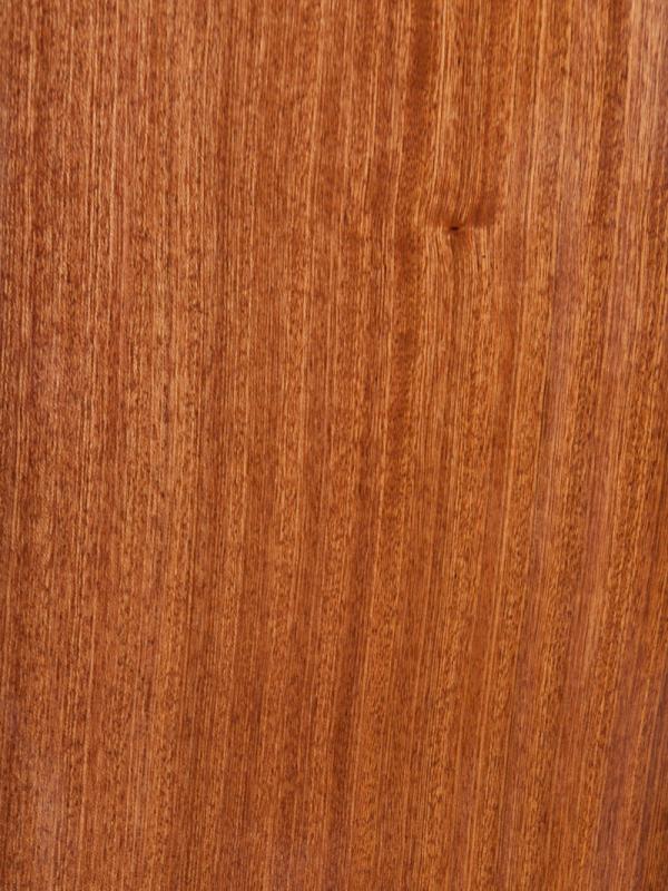
That, and it keeps the brain sharp. It will look killer when complete... I think I'm going to make my own plywood with an outer veneer of sapele like shown below.
This is one model I also want to build full scale too, so if I take the time to really improve this it will be worth the effort.
Editing materials library to replace the default appearance image. In my case I wanted to have an appearance of Sapele plywood, so I chose to edit the default oak appearance library entry.
Firstly you need an image to make an appropriate swatch to upload. It is best if your image is tile-able. It it very likely not. Mine was not. But the internet has everything including sites that make an image tile-able and all you have to do is upload your clean cropped image to remove any borders or labels. Process image, and if you picked a good site you can test the tiling. Now download and save your tile-able image.
Next select body or component that your have the default appearance applied to.
Right Click to bring up menu and select appearance.
Right Click on the Thumbnail image of the Material.
Select Duplicate.
Right Click on the Thumbnail of the Duplicate Material.
Select Edit.
Select Advanced.
Select the file name below the default image under the parameters section. Select new image to upload in its place.
Now double click on the image to bring up the image edit window. make changes necessary such as selecting tiling or not, image size and rotation etc. Click apply to check the result, click done and close window when you are satisfied with the results.
Below shows the default and the new sapele plywood applied to the near side of the trailer.
This image by the way shows the trailer body elevated 10" to leave space for a storage box base I have yet to model
Looks like Mahogany or Verolla to me. Are they related? Verolla is pretty inexpensive. Mahogany is the opposite. Never heard of Sapele. Where is it grown?
As much as I like old minis, I can't recall the last time I saw one, let alone a mini rear suspension. A decade or more maybe. Sad.
Timbren suspensions are state of the art suspension for trailers and off the shelf items with wide distribution network, so I can make more than one trailer eventually. And so I can design a slightly larger and heavily version of this trailer. In that case all I'd need is to step up to the next weight class of suspension and perhaps add brake hubs.
I also plan on eventually building a custom trailer with long slide outs to haul tools and a generator. It will have a slightly more robust frame, an alarm system large back up battery system, and will be able to be locked securely. When I get a rural property to build a custom home on I'll need a place to store tools until I can build a secure shop building.
Looks like Mahogany or Verolla to me. Are they related? Verolla is pretty inexpensive. Mahogany is the opposite. Never heard of Sapele. Where is it grown?
"Sapele is a timber originating from tropical Africa and grows to incredible dimensions; up to a height of 45m and a diameter of 10m. It is harder and heavier than African mahogany, weighing about 640kg/m3 when dried. This wood can also range from the Ivory Coast to the Cameroons and eastward through Zaire to Uganda
Sapele is quite a bit denser and nearly twice as hard. Not all of the Mahogany labelled species behave as well and they vary dramatically in density, color, and stability. However, the comparison to Mahogany as an outstanding exterior grade wood that has a rich reddish-brown heartwood holds true. Sapele is most often used as a window and door material because it is so stable and almost completely rot and weather resistant. The grain and pore structure is tighter than Genuine Mahogany so Sapele also serves as a great substrate for painted surfaces. "
Architects love sapele for its hardness and durability and lovely tight straight grain, especially windows, doors, outdoor decking and railings. It is great stuff.
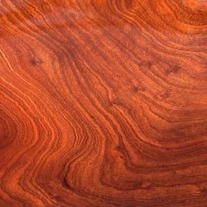
I love the look of the rotary cut plywood that I can get in Lloyd's certified marine grades in addition to okoume mahogany. Quarter sawn (on the right) looks significantly different. I've purchased veneers before of both types of cuts.
My Mom inherited a rosewood cylinder top desk that had panel inserts very reminiscent of the figure above. similar but superior to the one below. I guess that is where I grew to appreciate the look. I should make a model of that desk for fun.
Oh, I didn't say that it was. Just that it looks like it. And also wondered if it was related.
Awesome that it grows that fast and gets that big and yet is very hard.
Your mother's desk is beautiful.
Nice stuff!
I don't know where I got my love of nice wood and rock. Odd that I never heard of Sapele before. Too bad I am so old. I love to learn about new things. I feel like I barely touched a spot on the surface of everything I'd like to know.
There is a fellow offering design services whom I'd ask to model something for me but it would violate US and CDN intellectual property laws. From what I understand I can copy the design for personal non-commercial use but others can't provide commercial services that relate to manufacturing designs covered by IP rights.
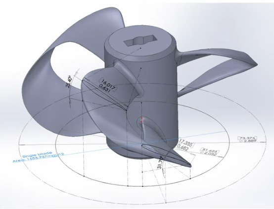
To model what I want requires lofting skills that are currently beyond me.
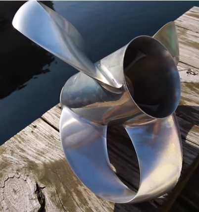
I don't know if anyone else has seen the marine propellers developed Sharrow marine, but they are revolutionary, and me being me, I just want to manufacture some to use on model boats and an electric drive for a kayak.
Now MIT's Lincoln lab has created and patented a similar type of propeller for aviation use, specifically in their case drones. They call them torroid props. There is a huge reduction in noise due to minimises tip vortices. Also greater efficiency by about 20% without any design work to optimize efficiency being done yet.
These new props are a wet dream for those who use micro drones for urban peeping. I think I can model these far simpler props but not the marine ones that I have been looking at the past few years
Now what I really want to know is does the new style propeller reduce the torque on the hull? I don't think it would....
I started learning how to model regular props in order to try to design a counter rotating drive with dual inline propellers to use on a canoe. Maybe I should aim really high and try a counter rotating sharrow propeller drive?
Beats me. I've not seen this before. If the prop increases lift or thrust with less input torque required, (ie more efficient) it should reduce torque on the hull for the same performance. However, most applications seek to increase performance to take advantage of the improved efficiency so I wouldn't really expect any improvement.
Are those things available for conventional outboard engines?