TorontoBuilder
Sapientia et Doctrina Stabilitas
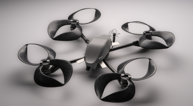
Yes, they are now for sale for larger outboards, and some inboard engines.Beats me. I've not seen this before. If the prop increases lift or thrust with less input torque required, (ie more efficient) it should reduce torque on the hull for the same performance. However, most applications seek to increase performance to take advantage of the improved efficiency so I wouldn't really expect any improvement.
Are those things available for conventional outboard engines?
caveat being they cost an arm, leg and both testicles... or in monetary terms $4999 USD each... hate to have twin outboards.
okay yes there should be less torque, but I want to eliminate it almost entirely since turning a canoe with a rear mounted motor presents a significant capsize danger due to the torque, the hull shape and the pivot point