• Spring 2024 meetup in Calgary - tentative date Saturday, April 20/2024. Other regions are also discussing meet ups. If you want one in your area get going on organizing it! discussion
  • We are having email/registration problems again. Diagnosis is underway. New users sorry if you are having trouble getting registered. We are exploring different options to get registered. Contact the forum via another member or on facebook if you're stuck. Update -> we think it is fixed. Let us know if not.
  • Spring meet up in Ontario, April 6/2024. NEW LOCATION See Post #31 Discussion NEW LOCATION

Still learning new things in fusion 360 regularly...

TorontoBuilder

Ultra Member
The renderings look Dark Knight badass. Look forward to the print or whatever you decide to prototype.
My eye wants fillets adjacent to the hub
View attachment 31134

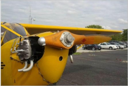
I hear you, and I had thought of adding fillets at first but while doing my lofts I noticed something I can do that will provide an even better result. similar to the image below of the blade root chord.

1677175344208.png

To achieve the best results it requires more tweaking and projecting paths onto the hub to start the loft from. The goal is total bad ass propeller. If this tests well against a standard 5040 prop I've already drawn perfect foils in the sketches that need only be changed from construction lines to solid lines in order to loft the new ideal propeller from which a mould can be made on cnc mill.
 

PeterT

Ultra Member
Premium Member
F360 might behave different than apps I've run. But it might be helpful if the root of the blade was defined completely inside (independent of) the hub. Loft it out as you are doing, join as a solid or separate bodies or whatever. I'm trying to say make the blade root so it is not associated with the hub itself by a projected curve or stitched surface. If you have difficulties filleting blade & hub, its very likely related to this issue. Its better to let the software calculate surface intersections when possible rather than trying to drive it. If my description isn't clear, I'm trying to say in airplane lingo: position the wing root geometry inside the fuselage body as opposed to transpose sketching the root onto the fuselage & using that as part of loft.

Fillets on bodies like this can be tricky too. If it fails to wrap or look right & you have exhausted different kind of varying fillets, usually its a trailing edge issue. A lot of the airfoil coordinate systems are like a single 100,0 point, which means an infinitely thin line. Or TE is truncated off square to match a real world mold. I found it best to round over the TE or some other fix.

Another potential lofting issue is when you have varying camber/reflex between sections. Here you really need the same number of control points defining the upper & lower foil sections, typically as % of chord. That way (software dependent) you can apply additional surface control curves connecting these upper lower positions. Think of it like a 25% spar, a 50% spar. Because just using LE & TE curves & foil sections can be insufficient. It may look pretty but can be a bogus surface aerodynamically. Hope this makes sense.
 

TorontoBuilder

Ultra Member
Thinking back over the modeling projects I have made over the past 20 years that I could have used fusion 360 to make things much faster and with far greater flexibility makes me want to revisit past projects and redo them..

The first R/C blimp I made gave me no end of fits trying to create the proper curved segments to fit together to make the desired blimp shape.... I had to settle for symmetrical shape. I could knock out such a plan now in an hour or so. The same with airfoil kite wings and intend to design a hybrid wing for a model paramotor
 

TorontoBuilder

Ultra Member
F360 might behave different than apps I've run. But it might be helpful if the root of the blade was defined completely inside (independent of) the hub. Loft it out as you are doing, join as a solid or separate bodies or whatever. I'm trying to say make the blade root so it is not associated with the hub itself by a projected curve or stitched surface. If you have difficulties filleting blade & hub, its very likely related to this issue. Its better to let the software calculate surface intersections when possible rather than trying to drive it. If my description isn't clear, I'm trying to say in airplane lingo: position the wing root geometry inside the fuselage body as opposed to transpose sketching the root onto the fuselage & using that as part of loft.

Fillets on bodies like this can be tricky too. If it fails to wrap or look right & you have exhausted different kind of varying fillets, usually its a trailing edge issue. A lot of the airfoil coordinate systems are like a single 100,0 point, which means an infinitely thin line. Or TE is truncated off square to match a real world mold. I found it best to round over the TE or some other fix.

Another potential lofting issue is when you have varying camber/reflex between sections. Here you really need the same number of control points defining the upper & lower foil sections, typically as % of chord. That way (software dependent) you can apply additional surface control curves connecting these upper lower positions. Think of it like a 25% spar, a 50% spar. Because just using LE & TE curves & foil sections can be insufficient. It may look pretty but can be a bogus surface aerodynamically. Hope this makes sense.
Your post makes sense. And yes it is essential to have exactly the same number of control points or you get unexpected twists or the loft intersects itself and fails.

In my first go the loft start at a plane just inside the hub. I now want this to be a start on a curved plane at the hub. I think that will yield the result I want.

But if that fails I can just use fillets.

I examined my lofts using segment analysis so I think the performance will match the looks, but I will validate the design with testing.

Post printing my plan was to sand off the truncated flat bottom to obtain as sound a trailing edge as possible. I've been wondering if it may be worth sanding the prints smooth and putting a 1.5 ounce fiberglass weave over the underside of the blades and coating it all in epoxy resin.
 

PeterT

Ultra Member
Premium Member
You might want to look into D-sub modelers for funky surface stuff. Rhino had a plug-in but it may even be fully integrated into their current <cough get student cough> version. You could develop in there & export into another modeler, it support many file formats. Rhino is relatively simple to use but its old school non-parametric. D-sub is pretty niche but it has its place. Not sure if there is an equivalent to F360, probably costs money. There is some degree of crossover to what 'good' conventional CAD modelers do surface control wise. The gap was wider in the past but sub-D is kind of cool if you are into that quasi-freeform organic swervy stuff, but still makes good quality NURBS surfaces.
 

PeterT

Ultra Member
Premium Member
sanding the prints smooth and putting a 1.5 ounce fiberglass weave over the underside of the blades and coating it all in epoxy resin.
I'm not a 3DP guy but have followed lots of 3DP RTF model efforts. Seems like the filament material, at least the common stuff, is a bear to get anything to stick to reliably. I had some self designed custom servo mounts printed by a buddy. I tested every glue in my arsenal & just didn't get a warm & fuzzy it would stay put over time on something critical so abandoned using them. Its like it has natural mold release properties. 1.5 might help but isn't a lot. Maybe print using one of the more specialized filaments, the CF blended goop maybe? My friend was big into robots & he said everything printed failed eventually vs a piece of aluminum unless it was quite robust & thick, mind you that may have been the application.
 

TorontoBuilder

Ultra Member
You might want to look into D-sub modelers for funky surface stuff. Rhino had a plug-in but it may even be fully integrated into their current <cough get student cough> version. You could develop in there & export into another modeler, it support many file formats. Rhino is relatively simple to use but its old school non-parametric. D-sub is pretty niche but it has its place. Not sure if there is an equivalent to F360, probably costs money. There is some degree of crossover to what 'good' conventional CAD modelers do surface control wise. The gap was wider in the past but sub-D is kind of cool if you are into that quasi-freeform organic swervy stuff, but still makes good quality NURBS surfaces.
I'm not sure I want to mess with other programs at the moment, and yes sub-d is now fulling integrated into Rhino I believe.

Fusion uses NURB surfaces, except the t-splines are more advanced and allow additional options to terminate rows of control points where less details are required. In my case I really needed minimal control points for the prop. I also could not figure out how to use standard propeller software to make looped propellers.

As I get older I keep busy with things like fusion to keep my brain sharp... but I dont need to be super sharp to the point I want to try too many new software programs. I'd much rather get onto making things that have an end goal I'd enjoy. For instance I love kiting, and I like kite aerial photography... but dont love it due to physical limitations and the instability of KAP camera rigs.

That lead me to want to make an R/C blimp camera rig, and I did have some success there but helium is too precious to waste and tank rentals were too expensive so when I saw the first R/C paramotor model I thought that is it... that's just what I want. They're quieter than drones, they're fun to fly, and the right size can lift my DSLR with no issues, and I can fly one at a large distance with the right radios.

So really, if this prop design works as well or better than standard that is a win in my books and goes a ways toward my project goals.

Just look how fun this looks:


TorontoBuilder

Ultra Member
I'm not a 3DP guy but have followed lots of 3DP RTF model efforts. Seems like the filament material, at least the common stuff, is a bear to get anything to stick to reliably. I had some self designed custom servo mounts printed by a buddy. I tested every glue in my arsenal & just didn't get a warm & fuzzy it would stay put over time on something critical so abandoned using them. Its like it has natural mold release properties. 1.5 might help but isn't a lot. Maybe print using one of the more specialized filaments, the CF blended goop maybe? My friend was big into robots & he said everything printed failed eventually vs a piece of aluminum unless it was quite robust & thick, mind you that may have been the application.
yeah I figure a 3d printed prop will only last long enough to perform thrust testing unless the prop speeds are kept really low. Unlike a drone a paramotor uses far less thrust and lower rpms so I figured the fine fiberglass may add to the tensile strength and help keep the layers bonded.

One thing that may help improve the adhesion of coatings is a post printing heat treatment (re-melt) I've been thinking about that is a hybrid between the bake the part while packed in powdered salt, and the metal castings method of making cores using sodium silicate and CO2 gas.

The method would involve mixing waterglass and ultra fine sand to make the traditional metal casting cores. Then lightly tamping a layer of the sand into the mould, then taking the part and pushing it firmly into the sand to leave an indentation in the shape of the part. Then the part is removed, and spritzed with water and the cavity in the mould is dusted with a blend of milled glass fibers between 0.009 and 0.039" long.

The part is then placed back into the mould and pressed down firmly with a tamper, and then given a further spritz of water, to aide glass fibers in sticking to the part when it is further ducted on the top side. Then more of the sand and sodium silicate mix is packed on top of the part as firmly as possible without distorting or breaking the part. Then the mould is fumed with CO2 to solidify.

This mould is then baked in a heat treat oven or toaster to reflow the PLA better bonding the filament layers and causing some of the milled fibers to become embedded in the PLA. If done well and with very fine sand the part surface should be fairly smooth and covered with shaggy fibers that would aide adhesion of a later coating of epoxy resin which may or may not be mixed with more glass fibers, or used with super light cloth.

Something I'll test out soon anyway to see how it works.
 

Dan Dubeau

Ultra Member
Sub d is now fully integrated into rhino. T splines used to be a plugin way back (wicked cool, and cheap for the time), then autodesk bought it, and integrated it into f360. I do not have a current seat of rhino, only 5.0, but am thinking about upgrading to 7 shortly. Mostly to play with sub d for lure design. Amazingly powerfull program for such a cheap price. Been a user since 2.0 and alway reccomend it. It does have a few drawbacks though, and for that reason is never my only cad programm, but for surface modeling it punches way above it's price point.
 

PeterT

Ultra Member
Premium Member
Oh ya Autodesk bought T-Splines a while back didn't they? So McNeel somehow negotiated... it back to itself within Rhino?
Is T-splines capabilities baked into the most basic version of Fusion or add-in with their more commercial flavors?
The world is changing too fast for me. Next you're going to tell me there's a Windows-11 LOL
 

Dan Dubeau

Ultra Member
I have no idea the inner working of the deal, just what I read when I tried to find the t-splines plugin again a few years back. I couldn't even find a pirate copy to play with, yargh. Don't know if the new sub d built into rhino is in any way related to the old t splines plugin other than it does similar stuff. I have a "user" level knowledge of this stuff lol, I don't care to know how it all works on the inside, nor would I really understand it.
 

TorontoBuilder

Ultra Member
Oh ya Autodesk bought T-Splines a while back didn't they? So McNeel somehow negotiated... it back to itself within Rhino?
Is T-splines capabilities baked into the most basic version of Fusion or add-in with their more commercial flavors?
The world is changing too fast for me. Next you're going to tell me there's a Windows-11 LOL
T-splines are in the most basic fusion.

Speaking of change, my first cad computer was dos based, with dos based autocad. When windows first came out I didn't want to buy new high end computer and new ACAD to run on it but was curious about a GUI so I bought a middle of the road back up computer, and the first version of a program call autosketch for windows from autodesk. That program was so easy and fast for simple design work I did most of my hvac designs on it instead of autocad. The downside was the limited output choices. My wife hated the sound of my pen plotter... she hated it so much she didn't object to D size inkjet plotter in our living space. Now people are reinventing the pen plotter wit their cnc machines. Go figure
 

TorontoBuilder

Ultra Member
I decided my 5040 toroidal propeller design had room for some improvement, especially in regards to the airfoil profile which will benefit from a slightly thicker cross section.

So I replaced the original ogival airfoil with a reliable NACA2415 airfoil profile sections. The NACA profile transitions to the base in a smoother arc with no jut forward on the foot, so it can be printed and run without sanding.

I also tweaked the sweep of the blades to be wider towards the base so that the design is closer to that of MIT. I think that the triloop design may not be as good as the first variant, but testing will verify what really is best.

Somewhere between the two designs is likely the best triloop propeller design. So maybe another version will be in the works after this one.

5040 Triloop NACA_2415 3.PNG


5040 Triloop NACA_2415.PNG


5040 TriLoop NACA2415 2.PNG
 

PeterT

Ultra Member
Premium Member
Its hard to tell from picture angle, but are the 2 blades in succession at same pitch angle? If so, isn't there some biplane effect at this short inter-blade distance that the downstream blade should be at a slightly different pitch if its seeing a slightly different wake angle from upstream blade?

1677525916942.png
 

TorontoBuilder

Ultra Member
Its hard to tell from picture angle, but are the 2 blades in succession at same pitch angle? If so, isn't there some biplane effect at this short inter-blade distance that the downstream blade should be at a slightly different pitch if its seeing a slightly different wake angle from upstream blade?

View attachment 31368

I've not seen anything like that with a multi bladed propeller... but I'm very inexperienced with this type of design.

I tried as much as possible to determine how MIT modeled their propellers as well and as far as the blade shape and pitch I think I have my design very close.

Anyway, testing will tell the tale.

I have standard glass filled nylon 5040 propellers, and I will be designing a reference propeller of of the standard 5040 design, as well as the Biloop and triloop versions all to be 3D printed using SLA in Accura Xtreme White 200. All will then be thrust tested using a thrust test stand similar to Tyto robotics 1580 stand.
 

PeterT

Ultra Member
Premium Member
Multiblade is a deep aerodynamic rabbit hole. Most of the references I have come across relate to air as the medium, aviation props, so water/boat props would be very different again. There is a misconception that more blades is 'better' because that show the math works. But like most engineering things, depends on the goal, constraints & assumptions. More what? More thrust?, efficiency? efficiency within a specific operating band? material constraints? dimensional constraints? etc. This was actually well understood at tail end of piston engine development WW2 era. Power levels became insanely large to the extent conventional props could not not adequately absorb that power & convert into proportionately more thrust. The theoretical prop diameter would be many times the wingspan. So you see contras & complex variable pitch mechanisms & other interesting solutions where interference effects & tradeoffs were weighed. By then, gas turbines were already showing the new way.

On the other end of the spectrum in model world (where I became familiar), counterweighted single blade props have been established to benefit. It started with high revving 2-S engines that make peak power at +40K rpm when homebrew carbon fiber designs could take the load without shedding. I saw it in early electric speed stuff for parallel reasons. Low cell count (voltage) meant high KV motor winds = high rpm. All old news now, they are all loud as hell.


TorontoBuilder

Ultra Member
Multiblade is a deep aerodynamic rabbit hole. Most of the references I have come across relate to air as the medium, aviation props, so water/boat props would be very different again. There is a misconception that more blades is 'better' because that show the math works. But like most engineering things, depends on the goal, constraints & assumptions. More what? More thrust?, efficiency? efficiency within a specific operating band? material constraints? dimensional constraints? etc. This was actually well understood at tail end of piston engine development WW2 era. Power levels became insanely large to the extent conventional props could not not adequately absorb that power & convert into proportionately more thrust. The theoretical prop diameter would be many times the wingspan. So you see contras & complex variable pitch mechanisms & other interesting solutions where interference effects & tradeoffs were weighed. By then, gas turbines were already showing the new way.

On the other end of the spectrum in model world (where I became familiar), counterweighted single blade props have been established to benefit. It started with high revving 2-S engines that make peak power at +40K rpm when homebrew carbon fiber designs could take the load without shedding. I saw it in early electric speed stuff for parallel reasons. Low cell count (voltage) meant high KV motor winds = high rpm. All old news now, they are all loud as hell.


all very interesting and mostly beyond my skills so I've done what I had the skills to do only.

I had seen counter weighted single bladed propeller designs and never took them seriously.
 

PeterT

Ultra Member
Premium Member
Yup just have fun & enjoy the process.
I forgot my favorite picture. I don't think it caught on LOL. Now was it a conscious R&D thing, or did guy get a tip strike throwaway and said 'I can make that work'!
 

Attachments

  • SNAG-2023-02-27 7.50.21 PM.jpg
    SNAG-2023-02-27 7.50.21 PM.jpg
    59.2 KB · Views: 4

Susquatch

Ultra Member
Administrator
Moderator
Premium Member
Yup just have fun & enjoy the process.
I forgot my favorite picture. I don't think it caught on LOL.

Hey! With only one blade to shoot through, they could have had faster machine guns!

I wonder what that would have sounded like? Prolly a bit like my grandma telling me not to touch the cookies she just baked. Ehh Ehh Ehh Ehh. LOL!
 
Top