-
Scam Alert. Members are reminded to NOT send money to buy anything. Don't buy things remote and have it shipped - go get it yourself, pay in person, and take your equipment with you. Scammers have burned people on this forum. Urgency, secrecy, excuses, selling for friend, newish members, FUD, are RED FLAGS. A video conference call is not adequate assurance. Face to face interactions are required. Please report suspicions to the forum admins. Stay Safe - anyone can get scammed.
-
Several Regions have held meetups already, but others are being planned or are evaluating the interest. The Calgary Area Meetup is set for Saturday July 12th at 10am. The signup thread is here! Arbutus has also explored interest in a Fraser Valley meetup but it seems members either missed his thread or had other plans. Let him know if you are interested in a meetup later in the year by posting here! Slowpoke is trying to pull together an Ottawa area meetup later this summer. No date has been selected yet, so let him know if you are interested here! We are not aware of any other meetups being planned this year. If you are interested in doing something in your area, let everyone know and make it happen! Meetups are a great way to make new machining friends and get hands on help in your area. Don’t be shy, sign up and come, or plan your own meetup!
You are using an out of date browser. It may not display this or other websites correctly.
You should upgrade or use an alternative browser.
You should upgrade or use an alternative browser.
Schematics and Circuit Board layout with Fusion 360
- Thread starter Tomc938
- Start date
Wow!How many is 'volume'? 10? 100?
I guess I mean how would you connect different "sections" of a machine, or maybe they are separate machines, together. Just musing here - Say your band saw has a control to cut up stock, and a robot arm to grab the pieces and load them into your mill with an automatic vise, the program runs on the mill, and then the arm unloads the part and puts it into the spray booth where it is painted. How would scenarios like this be managed? A single master control controlling those machines to do their operations - or would each machine tell the next - ready for you - and then the first machine gets on with the next operation. @Susquatch I bet you have several answers and yes I'm dragging you out of retirement to think about it! 🙂
If you talk to LinuxCNC people they will run everything with modules inside the LinuxCNC environment. The problem with that is it's so centralized.
Both MODBUS and CAN (Controller Area Network) were designed to break a complicated project into modules; each which could be developed and tested independently.
So how do those systems work?
Let's pretend you have a tool changer for a milling machine. Most of the systems have that as part of the CNC system. But what if we made it modular?
CMC system requests Tool #17 Request.
Tool Changer replies with Busy. Tool Holder brings Tool #17 into a tool swap location.
Tool Holder replies with Ready.
Tool Changer sees Ready and moves Tool Holder onto Tool in Mill and asks DrawBar To release current tool with a Request.
Drawbar reports Busy. Releases the tool and reports Available.
Tool Holder grabs tool from spindle and swaps with Tool Changer Tool and reports Ready.
Finally Tool Changer reports Ready to the CNC system that a new tool has been loaded. Then grabs the old tool and places it into the carousel.
Or something to that effect. Made it up as I wrote it.
The point is the Request/Busy/Available/Ready sequence can be used as CAN bus or even MODBUS messages to independent modules that do certain operations. Each module can be tested, improved etc without impacting the overall system. The handshaking messages between modules don't really change.
Hopefully that makes sense?
FWIW, I am using MQTT with ESP32 based hardware nodes to provide local compute/actuate/sense functions with a distributed broker system running on a Teensy 4.1 MCU. The benefit is a much simpler m/c control system that is inexpensive and easily extended, even between machines and their support systems such as coolant, lighting, pumps, conveyors, packers, etc.Wow!
If you talk to LinuxCNC people they will run everything with modules inside the LinuxCNC environment. The problem with that is it's so centralized.
Both MODBUS and CAN (Controller Area Network) were designed to break a complicated project into modules; each which could be developed and tested independently.
....
....
Or something to that effect. Made it up as I wrote it.
The point is the Request/Busy/Available/Ready sequence can be used as CAN bus or even MODBUS messages to independent modules that do certain operations. Each module can be tested, improved etc without impacting the overall system. The handshaking messages between modules don't really change.
Hopefully that makes sense?
I developed the system using open-source libraries and modules specifically to distribute tasks and decentralize the control of a machine, to reduce wiring and improve telemetry. This type of system has built-in redundancy and 1-10ms response time.
Don
Tomc938
Ultra Member
So time for an update:
I took a run at those boards, but man the components are small!
So I was waiting for connectors to comes through CP, and they arrived a couple weeks ago.
I tried hand soldering some SMD components about same size as were used in the board design and realized I wasn't able to do this. Read about using solder paste for these smaller components, so I ordered some and when it arrived the first little bit of the paste worked really well. Came out smooth and in a controlled fashion, and when I hit it with heat it flowed well and made good connections. But then I seemed to hit a dry patch in the paste. Could hardly push it out of the syringe - it came in a 5 ml type syringe. Was able to make it work, but it was harder to control, and I had to push so hard that I ended up a good chunk of the night with the arthritis in my thumbs killing me. When it came time to connect the large connectors with a soldering gun, one of the resistors popped up and ended pointing straight up on one pad. Got that fixed, but as I looked at things I had some concerns:
1) With poor control on the amount of solder dispensed, did I maybe had a dead short I could not see?
2) With the small components, did I have a good connection on each pad?
3) Was I ready to miss sleep a couple more nights due to thumb pain to finish populating the board ?
4) If the adaptor didn't work, how would I ever figure out where the fault was?
@slow-poke was very helpful along the way, answering all my newbie questions and offering advice. At a certain point I think he realized (before I did) that I was in over my head and offered to populate the boards I needed with the components if I sent him everything I had gathered. It was hard to throw in the towel, but I knew I was beat. Had a nice visit with him on the phone, and found out we lived a couple miles apart in Winnipeg!
So last week I packaged everything up and sent it out to him. Ordered some replacement connectors from Ali that will ship direct to him. He has also graciously offered to test the boards with scales and see how they work.
Assuming the boards work (it is a schematic from the internet, after all) I have 6 additional boards I will be making available to anyone who wants one or two at my cost ($2 each) and $10 to @slow-poke for the design work he did to make the boards manufacturable. Can ship in an envelope also at cost. Cost of the components is not a lot. (I think $10 per board including shipping from Digikey) You do have to be sure that you can source an ESP32 WROOM-32U. Check the pin out on the board, because a couple I saw that said there 32U had a very different pin out and would not have worked. (about $10 on Ali or Amazon) You also have to be confident in your soldering skills. Parts are SMALL!
Let me know if you would be interested in one or two and I'll keep you posted as things progress.
I took a run at those boards, but man the components are small!
Thanks for asking! I kind of forgot about this thread with everything happening with them the last few weeks.Hi Tom. Have you had a chance to work on your boards?
So I was waiting for connectors to comes through CP, and they arrived a couple weeks ago.
I tried hand soldering some SMD components about same size as were used in the board design and realized I wasn't able to do this. Read about using solder paste for these smaller components, so I ordered some and when it arrived the first little bit of the paste worked really well. Came out smooth and in a controlled fashion, and when I hit it with heat it flowed well and made good connections. But then I seemed to hit a dry patch in the paste. Could hardly push it out of the syringe - it came in a 5 ml type syringe. Was able to make it work, but it was harder to control, and I had to push so hard that I ended up a good chunk of the night with the arthritis in my thumbs killing me. When it came time to connect the large connectors with a soldering gun, one of the resistors popped up and ended pointing straight up on one pad. Got that fixed, but as I looked at things I had some concerns:
1) With poor control on the amount of solder dispensed, did I maybe had a dead short I could not see?
2) With the small components, did I have a good connection on each pad?
3) Was I ready to miss sleep a couple more nights due to thumb pain to finish populating the board ?
4) If the adaptor didn't work, how would I ever figure out where the fault was?
@slow-poke was very helpful along the way, answering all my newbie questions and offering advice. At a certain point I think he realized (before I did) that I was in over my head and offered to populate the boards I needed with the components if I sent him everything I had gathered. It was hard to throw in the towel, but I knew I was beat. Had a nice visit with him on the phone, and found out we lived a couple miles apart in Winnipeg!
So last week I packaged everything up and sent it out to him. Ordered some replacement connectors from Ali that will ship direct to him. He has also graciously offered to test the boards with scales and see how they work.
Assuming the boards work (it is a schematic from the internet, after all) I have 6 additional boards I will be making available to anyone who wants one or two at my cost ($2 each) and $10 to @slow-poke for the design work he did to make the boards manufacturable. Can ship in an envelope also at cost. Cost of the components is not a lot. (I think $10 per board including shipping from Digikey) You do have to be sure that you can source an ESP32 WROOM-32U. Check the pin out on the board, because a couple I saw that said there 32U had a very different pin out and would not have worked. (about $10 on Ali or Amazon) You also have to be confident in your soldering skills. Parts are SMALL!
Let me know if you would be interested in one or two and I'll keep you posted as things progress.
Tomc938
Ultra Member
As far as them populating the boards you order from them, I misread the website. It would be about $30 PER BOARD on an order of 10. Depends on how many discrete components and through holes there are.As I mentioned in the original post, components would be on top of this. This is just the assembly.
At least that's how I read the information.
And I think it's likely an introductory offer. Just based on life experience.
But if you had something you wanted to build a few of it would make sense, in my mind, to pay for the assembly. It was beyond my skills, that's for sure!
Hi Tom surface mount stuff takes a bit of learning but it is easier in the long run. The resistor popping up is called a tombstone. I use my rework heat gun with its smallest nozzle on decent heat.
Also for the syringe for the solder paste. I always electrical tape the end and put it in the fridge. It can dry out if left out in the open. I have also used the little rubber ends for them. There are 3d printed dispensers for the syringes as well. Those help so much.
Also for the syringe for the solder paste. I always electrical tape the end and put it in the fridge. It can dry out if left out in the open. I have also used the little rubber ends for them. There are 3d printed dispensers for the syringes as well. Those help so much.
Tell us, maybe tell us again, Tom what will these boards do for people, how to apply them and what other parts are needed, and what are you doing with the boards?So time for an update:
Assuming the boards work (it is a schematic from the internet, after all) I have 6 additional boards I will be making available to anyone who wants one or two at my cost ($2 each) and $10 to @slow-poke for the design work he did to make the boards manufacturable. Can ship in an envelope also at cost. Cost of the components is not a lot. (I think $10 per board including shipping from Digikey) You do have to be sure that you can source an ESP32 WROOM-32U. Check the pin out on the board, because a couple I saw that said there 32U had a very different pin out and would not have worked. (about $10 on Ali or Amazon) You also have to be confident in your soldering skills. Parts are SMALL!
Let me know if you would be interested in one or two and I'll keep you posted as things progress.
Tomc938
Ultra Member
Sure. A quick review: My mill and lathe came with DROs that kind of work, but not well, and they are 80's tech. The mill only had one axis that worked, and the lathe has lots of issues with burned out segments in the display.Tell us, maybe tell us again, Tom what will these boards do for people, how to apply them and what other parts are needed, and what are you doing with the boards?
After looking around for options, TouchDRO came highly recommended y several people on the board for whom I have great respect. So I looked into that as an option.
TouchDRO started with a freeware/open source type model I found attractive. The schematics and software to build the interface between the scales and the Android tablet that is used for the display are available from the developer for free. You can also buy pre-built adapters from the designer.
I wanted to go the self-built route, and so started using the design features of Fusion 360 to turn the schematic into a board design. Unfortunately, I only know enough about circuit design to come up with a reasonable looking layout that would be non-functional. That's when @slow-poke offered to design the circuit, having done this kind of thing as a career.
And that is a quick review that gets you up to the last couple of posts I just posted.
These adapter boards should allow you to connect various scales to an Android device to open up some pretty nice, highly capable DRO features at a fraction of the cost. See touchdro.com for more information in the setup.
You would need to add resistors, capacitors, ICs, power supply, case and an ESP-32 board to make it functional. If anyone is interested, I can send the parts list @slow-poke put together.
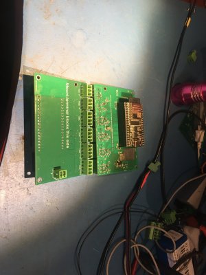
This is a project for someone who knows what they are doing. The boards are capable of connecting X,Y,Z and knee scales, as well as a touch probe and tach. Once you know what you want to connect, you would be able to figure out what you need to order. As far as scales, look to the webpage I mentioned for more information about what types of scales can be connected.
You will also need to have some basic understanding about terminal commands so you can flash the program to the ESP32 chip. The program is available for download. I have the steps needed to do this on a Mac computer, but a PC person would need to be able identify the comm port the chip is connected to. The code is in Python, but when I started I knew about nothing about Python and still got her done.
I'm willing to assist in the selection of an ESP32 chip. As I mentioned there are many configurations that are manufacturer dependent. And can also give some guidance as to how the boards are set up.
I also mentioned the parts you would be working with are small, so you have to be comfortable with that. Just so you know, here's a picture of the board I did. This was for my lathe, so I just did the X and Y axis. (a banana for scale would have been useless. Even a dime is kinda big)
Everything is in testing, so we'll need to wait and see how everything comes together.

slow-poke
Ultra Member
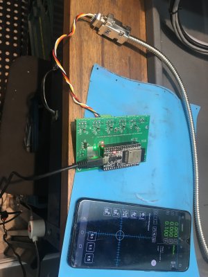
Update...
I finally found some time to populate and test one of the boards Tom sent.
Seems to work (I calibrated X, Y & Z to my scales).
The Bluetooth connectivity seems a bit iffy but that might be the cheap power adapter I used to power it, or perhaps the software is just not great, seems to be a common problem from my two minute Google sleuthing.
Tom do you need one or two boards?
Some parts are missing
Attachments
Tomc938
Ultra Member
Yeah!!!!Update...
I finally found some time to populate and test one of the boards Tom sent.
Seems to work (I calibrated X, Y & Z to my scales).
The Bluetooth connectivity seems a bit iffy but that might be the cheap power adapter I used to power it, or perhaps the software is just not great, seems to be a common problem from my two minute Google sleuthing.
Tom do you need one or two boards?
Some parts are missing
Just got home from our trip this evening, so your timing is impeccable.
The Bluetooth was a bit sketchy for me too, but once I connected once it seemed to work better.
I need two boards, one for the lathe and one for the mill.
I don’t remember if I told you, but I don’t need the boards fully populated. X, Y and Z on one, and X, Y and Z and rpm on the other.
If there are parts missing, please let me know what I owe you and I’ll square up when I send the etransfer for the shipping.
What Schematic Capture and Layout software have you used over all those boards you've worked on?You asked for suggestions and I have expertise in this area, I have designed many hundreds of complex boards so realize when I look at a circuit/layout I look at it critically.
0) The regulators are missing decoupling and may well oscillate, depending on type used.
1) I would replace the terminal blocks with plugable ones. They are inexpensive.
2) Wire opening should face outside edges.
3) I work from extensive proven libraries so I don't have to worry about things like incorrect pad hole size, that's just one (of many) problems you might encounter when using unproven libraries, or creating your own footprints. I would verify.
4) I don't use fusion, so I don't know how well the DRC works or how you have configured it?
5) I can't clearly see the schematic, can you post a higher resolution version.
6) Might want to check out AllPCB, they often have coupons for free small boards like this for new customers.
7) Through holes components are 1980's technology, SMT uses a fraction of the space, and should allow you to accomplish #2 above
8) Your decoupling capacitors are not where they should be.
9) Are you using a ground plane or just traces for ground? If traces how wide are they and have you considered the ground path?
10) auto-routers are cool to watch, but they generally result in a terrible layout.
11) Hand soldering a SMT version of that board would be trivial if you use 0603 min.
12) Good practice is to re-annotate the component designators in a logical fashion so you don't have to hunt.
13) Label individual terminal block signals
14) I don't see pin 1 indicators on silkscreen.
15) There is more, but I will stop, I'm a bit picky because my last job was as a consultant "fixing" stuff like this for others.
slow-poke
Ultra Member
Primarily Altium but before it was called Altium, originally it was called Tango in the 80's and then Protel and finally Altium.What Schematic Capture and Layout software have you used over all those boards you've worked on?
I have used several others; Pads ( what a complete POS), Orcad/Cadance (Pretty good), I also tried some of the free or cheap ones (you get what you Pay for) KiCad, Eagle etc. I find most of these pretty useless compared to Altium.
I also use Altium for 95% of my step file generation for 3D printing.
Good to know as I followed the same path although to be truthful I've never really gotten my head around Altium even though I know it's better than Protel 99SE Version 6. So I often start a drawing in Protel and if needed then migrate it to Altium.Primarily Altium but before it was called Altium, originally it was called Tango in the 80's and then Protel and finally Altium.
I have used several others; Pads ( what a complete POS), Orcad/Cadance (Pretty good), I also tried some of the free or cheap ones (you get what you Pay for) KiCad, Eagle etc. I find most of these pretty useless compared to Altium.
I also use Altium for 95% of my step file generation for 3D printing.
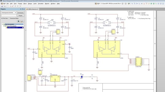
So for example I bought those little motor driver modules.

First thing to did was reverse engineer them and then figure out how to make them more reliable. Normally I've just posted a PDF of the schematic. But since @slow-poke uses Altium he can edit these now that I've added the files.
I may do a new PC board for this driver that fixes the errors and possibly even adds some features purely because at the moment the board with the terminal strips and motor driver is about $5 while just a brand new motor driver chip is $19. Even the Heat Sink is expensive. Therefore the idea is to add a socket for something like an ESP32 processor.
Just an idea. Have to keep that list of 42 projects populated. Anyway, if I do a new layout it would be great if @slow-poke had a look see at the PCB design when I'm done.
Attachments
Ah. That's a throwback to way back when. The main schematic was a .prj and the daughter schematics were .sch. I renamed the .prj to a .sch and then was able to open the file with selecting one of the intersection options. Also saved as Rev 5.0 rather than the older Protel 99SE 4.0 format.I normally send the; .sch, .pcb, and sometimes the .prj files for a project.
Very easy to generate the libraries from those if needed.
Not sure why your .prj files don't seem to be recognized by (my) Altium?
See if this opens for you.
Attachments
slow-poke
Ultra Member
Now that you mention that, I remember, that was quite a while back.Ah. That's a throwback to way back when. The main schematic was a .prj and the daughter schematics were .sch. I renamed the .prj to a .sch and then was able to open the file with selecting one of the intersection options. Also saved as Rev 5.0 rather than the older Protel 99SE 4.0 format.
See if this opens for you.
No problem opening the files, looks a bit like this.
Attachments
slow-poke
Ultra Member
Two boards tested and ready less C12.Yeah!!!!
Just got home from our trip this evening, so your timing is impeccable.
The Bluetooth was a bit sketchy for me too, but once I connected once it seemed to work better.
I need two boards, one for the lathe and one for the mill.
I don’t remember if I told you, but I don’t need the boards fully populated. X, Y and Z on one, and X, Y and Z and rpm on the other.
If there are parts missing, please let me know what I owe you and I’ll square up when I send the etransfer for the shipping.
E117-00a Schematic with some changes to the notes that reflects as built
E117-01a suggested (improved) schematic for future with less components and better performance for scales with differential signaling
Attachments
Yup. I ran into the same problem trying to open the .prj file. Odd actually. That used to work. I tried with Altium 17 and was able to 'open' the .prj file.Now that you mention that, I remember, that was quite a while back.
No problem opening the files, looks a bit like this.
Tomc938
Ultra Member
Well I am excited to say Jeff has built two of the boards and tested them and they work!
I ordered a batch of 10 as that was the smallest order number.
I have 6 spares. If anyone would like one, I can send it to you for postage plus $3 (my cost) per board.
I also can send the parts list so you know what to order. Word of warning: the components are mighty small. You need to be confident soldering surface mount components or it probably won't work.
Also, you need to order ESP32-DevKitC core board ESP32 development board ESP32-WROOM-32D. It has to be the exact part. There are lots of these boards out there, and the pinout are different. They re available on Amazon or Ailespress. (https://vi.aliexpress.com/item/1005...st_main.5.7de11802a0ILgT&gatewayAdapt=glo2vnm).
There is a bit of terminal UNIX stuff that needs to be done to install the software on the chip. I am willing to walk you through the steps. It's a bit involved.
I need another DRO like I need a hole my the head or 42 more projects but I am so tempted...Well I am excited to say Jeff has built two of the boards and tested them and they work!
I ordered a batch of 10 as that was the smallest order number.
I have 6 spares. If anyone would like one, I can send it to you for postage plus $3 (my cost) per board.
I also can send the parts list so you know what to order. Word of warning: the components are mighty small. You need to be confident soldering surface mount components or it probably won't work.
Also, you need to order ESP32-DevKitC core board ESP32 development board ESP32-WROOM-32D. It has to be the exact part. There are lots of these boards out there, and the pinout are different. They re available on Amazon or Ailespress. (https://vi.aliexpress.com/item/1005...st_main.5.7de11802a0ILgT&gatewayAdapt=glo2vnm).
There is a bit of terminal UNIX stuff that needs to be done to install the software on the chip. I am willing to walk you through the steps. It's a bit involved.
No John!!! Look at the picture... You have enough already...

No means no!
Stop it... The answer is still no....
I haven't even finished assembling the second DRO-550 much less the second DRO-350... The Unimat doesn't need a DRO at the moment....
Noooooooooo.