• Scam Alert. Members are reminded to NOT send money to buy anything. Don't buy things remote and have it shipped - go get it yourself, pay in person, and take your equipment with you. Scammers have burned people on this forum. Urgency, secrecy, excuses, selling for friend, newish members, FUD, are RED FLAGS. A video conference call is not adequate assurance. Face to face interactions are required. Please report suspicions to the forum admins. Stay Safe - anyone can get scammed.

Prusa mk4

- Can you change the orientation of the model within the printing software, or does the model have to be made in the best orientation for printing?
- Does the printing software automatically generate the necessary supports for things like undercuts, or are they manually added?
Yes to both (at least with Prusa's slicer), but with provisos.
1. You can change the orientation in the slicer, but if there's not already a "good" orientation in the part, you're up the creek. I went a put a small wiper ridge on one edge of a recent DRO bracket, and that, of course, blocked laying it down on that side, forcing a different orientation. Not catastrophic, but annoying to have a tall part to print instead of a nice flat one.
2. It can, though it tends to be pretty aggressive when you ask it to. You can paint on supports in the slicer and it will figure out how to support just those sections. It's also impressive how much empty air the LDM process can span with some materials, and how steep an overhang is possible before sagging starts.
 
I‘m modelling some parts for a friend who sends them off to be 3D printed before he gets them CNC machined.

I have a couple of questions about the printing (slicer?) software thats used:
- Can you change the orientation of the model within the printing software, or does the model have to be made in the best orientation for printing?
- Does the printing software automatically generate the necessary supports for things like undercuts, or are they manually added?
I like to do expansion and orientation in the CAD software. I am sure the printer software will compensate, but its better to control it yourself.
 
Something to keep in mind when using a 3D printer. It doesn't all have to be printed in one go. If you can, you are best off to visualize the nicest way to print it for max strength etc. and then create the parts separately. Krazy glue or even hotmelt or 5 minute epoxy can take care of reconstructing the model.
 
Thanks @PaulL , @Matt-Aburg & @jcdammeyer

I’m surprised that the printers software doesn’t “automatically” compensate for contraction of the different types of filament, or that it’s better to do this in the CAD software.

For a part like this, would the bottom or the top (with supports) be best for being up against the printer bed:
IMG_8861.jpeg

I have my guess, but since I don’t own a 3D printer I’m interested if my guess is correct.
 
I‘m modelling some parts for a friend who sends them off to be 3D printed before he gets them CNC machined.

I have a couple of questions about the printing (slicer?) software thats used:
- Can you change the orientation of the model within the printing software, or does the model have to be made in the best orientation for printing?
- Does the printing software automatically generate the necessary supports for things like undercuts, or are they manually added?
You can change the part orientation so that it’s best placed for printing.
Supports can be automatically generated as well when that setting is turned on in Prusa Slicr
 
Thanks @PaulL , @Matt-Aburg & @jcdammeyer

I’m surprised that the printers software doesn’t “automatically” compensate for contraction of the different types of filament, or that it’s better to do this in the CAD software.

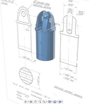
For a part like this, would the bottom or the top (with supports) be best for being up against the printer bed:
View attachment 43458
I have my guess, but since I don’t own a 3D printer I’m interested if my guess is correct.
Too many variables. Although I've seen some very beautiful 3D prints IMHO, it's still cheap plastic molding. And I use it all the time. But it's not even close to a part made with injection molded plastic. And there they design the mold so that shrinkage creates the correctly sized part.
 
Thanks @PaulL , @Matt-Aburg & @jcdammeyer

I’m surprised that the printers software doesn’t “automatically” compensate for contraction of the different types of filament, or that it’s better to do this in the CAD software.

For a part like this, would the bottom or the top (with supports) be best for being up against the printer bed:
View attachment 43458
I have my guess, but since I don’t own a 3D printer I’m interested if my guess is correct.
I wouldn't print this as a vertical part. Each layer is a weak point. There's no strength there. Think about splitting firewood. It won't split across the growth rings. You have to saw it into short pieces. Then split along the grain. The 3D printing has the same strength issues but opposite to a tree trunk.
 
I still don't understand why there isn't a demand for custom printing. I for one have asked for a couple years now, it seems like nobody takes custom orders. I've had some good luck with loading blocks from guys, but not so much good luck with anything else

Weird
 
I‘m modelling some parts for a friend who sends them off to be 3D printed before he gets them CNC machined.

I have a couple of questions about the printing (slicer?) software thats used:
- Can you change the orientation of the model within the printing software, or does the model have to be made in the best orientation for printing?
- Does the printing software automatically generate the necessary supports for things like undercuts, or are they manually added?

Thanks @PaulL , @Matt-Aburg & @jcdammeyer

I’m surprised that the printers software doesn’t “automatically” compensate for contraction of the different types of filament, or that it’s better to do this in the CAD software.

For a part like this, would the bottom or the top (with supports) be best for being up against the printer bed:
View attachment 43458
I have my guess, but since I don’t own a 3D printer I’m interested if my guess is correct.
Is the 3D printed part functional? or is it a visual, o to check fit? If only for looks, non stress testing, then this would be the most efficient way to print it. If the holes that go sideways take any stress, it will crack for sure, and so laying it sideways in two parts like @jcdammeyer says is the best way. Add some locators to the two halfs, protrusions-one half, pocket the other and glue.
 
I still don't understand why there isn't a demand for custom printing. I for one have asked for a couple years now, it seems like nobody takes custom orders. I've had some good luck with loading blocks from guys, but not so much good luck with anything else

Weird
There are always a couple of ads on Marketplace for people willing to print stuff here.
 
I still don't understand why there isn't a demand for custom printing. I for one have asked for a couple years now, it seems like nobody takes custom orders. I've had some good luck with loading blocks from guys, but not so much good luck with anything else

Weird
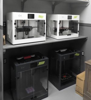
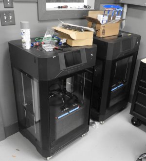
send me your prints.. I have vacant machines waiting. I can also design the parts if you need. 13.5 x 13.5 x 24 capacity on the large printers, 16.8 x 9.7 x 9.7 or 19 for the medium and small printers
 

Attachments

  • DSCN1845.JPG
    DSCN1845.JPG
    317.9 KB · Views: 12
  • DSCN1848.JPG
    DSCN1848.JPG
    372.7 KB · Views: 11
send me your prints.. I have vacant machines waiting. I can also design the parts if you need. 13.5 x 13.5 x 24 capacity on the large printers, 16.8 x 9.7 x 9.7 or 19 for the medium and small printers

Holy Crap Matt! That look amazing!
 
send me your prints.. I have vacant machines waiting. I can also design the parts if you need. 13.5 x 13.5 x 24 capacity on the large printers, 16.8 x 9.7 x 9.7 or 19 for the medium and small printers
What is the appropriate file format you require originating from a 3D CAD modeler?
 
What is the appropriate file format you require originating from a 3D CAD modeler?
I prefer native CAD, or X_T , STP. I can convert from just about any format with fusion if my CAD doesn't support it. I prefer to triangulate the model myself, as the free STL's are usually jaggedly. I convert the STL's with a 0.0001 tolerance and 1 degree on the angle, resulting in large STL, but very smooth product.
 
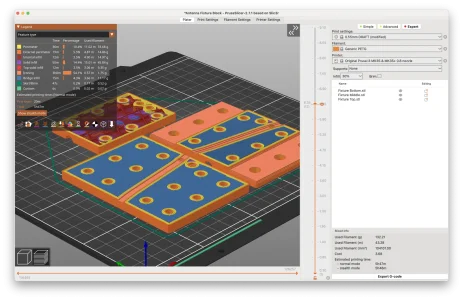
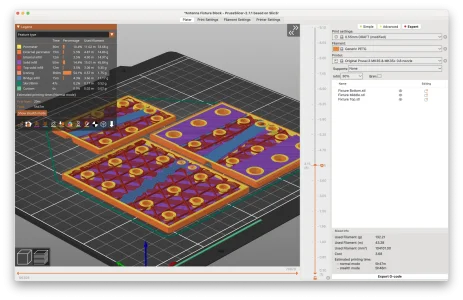
The slicers keep getting better. You could specify a lot of perimeters and a dense infill for the top 1/3 of the part and leave the bottom 2/3 with weaker settings.
 
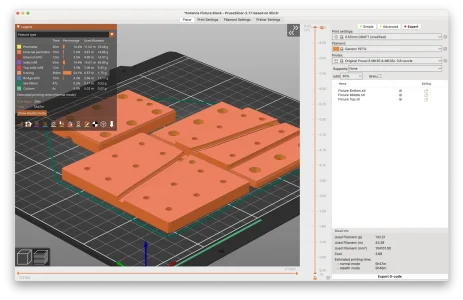
Just to get an idea. Below is slicer screen shots at different depths through the part. You can see the internal structure. This is with a 30% infill and 3 layers around the outside of the part (3 perimeters). All these details are controllable.
1706886464152.webp


1706886478261.webp

1706886491605.webp
 
Back
Top