• Scam Alert. Members are reminded to NOT send money to buy anything. Don't buy things remote and have it shipped - go get it yourself, pay in person, and take your equipment with you. Scammers have burned people on this forum. Urgency, secrecy, excuses, selling for friend, newish members, FUD, are RED FLAGS. A video conference call is not adequate assurance. Face to face interactions are required. Please report suspicions to the forum admins. Stay Safe - anyone can get scammed.
  • Several Regions have held meetups already, but others are being planned or are evaluating the interest. The Ontario GTA West area meetup is planned for Saturday April 26th at Greasemonkeys shop in Aylmer Ontario. If you are interested and haven’t signed up yet, click here! Arbutus has also explored interest in a Fraser Valley meetup but it seems members either missed his thread or had other plans. Let him know if you are interested in a meetup later in the year by posting here! Slowpoke is trying to pull together an Ottawa area meetup later this summer. No date has been selected yet, so let him know if you are interested here! We are not aware of any other meetups being planned this year. If you are interested in doing something in your area, let everyone know and make it happen! Meetups are a great way to make new machining friends and get hands on help in your area. Don’t be shy, sign up and come, or plan your own meetup!

JCDammeyer's 42 projects

I was looking for a specific photo for a totally different project ran into these old ones. Making a heat sink for my sailboat voltage monitor.

Pouring 4 of them.

HTSNK.JPG


The result of the pour and installed on the module.
HTSNK1.JPG
HEATSINK.JPG
 
Any pictures of the yacht?
This was it. An O'Day 28'.
1745619367435.png


The alternator/regulator failed and the alternator was a set of coils under the flywheel. It was easier to rebuild the front pulleys and add an alternator onto the front of the engine.
Which meant casting brackets,
1745619449784.png


Casting and machining pulleys.
1745619637475.png


All done on the Gingery Lathe before it was even finished.
1745619681260.png
 
Nice! I've never sailed one that big.

Is what you're describing just a magneto?
No it was a 3 phase alternator on the BMW Diesel. Magnets in the flywheel and stationary coils inside that area out to the regulator. Cost of repair parts was off the charts. A friend gave me a brand new tractor alternator and regulator that was originally intended for home built aircraft. Just had to make it fit.

We did our cruise and learn in Comox on a Catalina 27 in spring of 1985. Then bought the HotFoot 24 in summer of 86 after Expo 86. Sold it when we moved to The Netherlands in 1992. Bought the O'Day 28 when we moved to Victoria in 1997. Sold it when it got to the point where the resale value was less than one year moorage.
I was serving in the CF at Comox then! (1985!) VU-33 Squadron, I was fixing Trackers and T-33's.

Funny how close paths can cross without meeting! Had a friend that was crewing on a pretty large sailboat invited me out for one of their practice sessions. Was fun, but the money (that I didn't have)was way above my affordability, even trying to be crew, and the allure wasn't there as it need to be to have a fella pour all his spare coin into the hole in the water where the money goes....

Pretty much been my experience with glass slipper gliders, and several other avenues of burning money. LOL! Interesting enough, until you have to meet the price of admission. If it burns in your soul, no price will ever stop you. Sailing wasn't it for me!
 
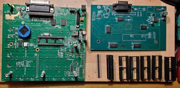
Yahoo! The PC boards arrived. Now to make sure I have all the parts and assemble one. The software was written for a slightly different PIC32 but should port easily enough assuming the board even works.

If it does it means I can retrofit my ELS to use a quadrature encoder with a proper quadrature counter module and not lose the ability to turn high RPM like the Electronic Gearing Systems that use an Arduino and are restricted in speed.

There's also a USB connector on this so theoretically I should be able to add code to read a USB drive and update software that way along with interpreting G-Code.
1746034903453.png
 
Almost all the parts installed. The crystal is just sitting there while I wait for a 12Mhz part. That and a few others. Don't want to install the PIC32 until everything else has been tested. I've ordered 15mm stand offs and a few other parts to try and get the two to fit together.

Biggest mistake was the optical isolators; wrong foot print. But they aren't important for the first prototype. I had ordered 5 PC boards which was their minimum. They delivered 8 pieces.

1746083402431.png
We'll see how it goes.
 
Almost all the parts installed. The crystal is just sitting there while I wait for a 12Mhz part. That and a few others. Don't want to install the PIC32 until everything else has been tested. I've ordered 15mm stand offs and a few other parts to try and get the two to fit together.

Biggest mistake was the optical isolators; wrong foot print. But they aren't important for the first prototype. I had ordered 5 PC boards which was their minimum. They delivered 8 pieces.

View attachment 63978We'll see how it goes.
So there's nothing COTS that let's me easily extend the socket pins from the original board to the new one. I used a machined high quality socket for the base ELS with the idea that maybe some time in the future I could insert these special rows of machined pins into the socket and into the companion board. But nothing is long enough to reach.
After much thinking it suddenly hit me. I should 3D print the pin holder and use 24g solid wire for the pins. They are a perfect fit for the original socket and can be soldered into the board as a special header.

The slots along the sides are for some epoxy to just hold them in place. Bevel of 45 degrees so I don't have to use support filament. Printing will be done in 11 minutes. Now I wish I had some 24g solid wire. Time to head out to buy some.

1746135278927.png
 
So there's nothing COTS that let's me easily extend the socket pins from the original board to the new one. I used a machined high quality socket for the base ELS with the idea that maybe some time in the future I could insert these special rows of machined pins into the socket and into the companion board. But nothing is long enough to reach.
After much thinking it suddenly hit me. I should 3D print the pin holder and use 24g solid wire for the pins. They are a perfect fit for the original socket and can be soldered into the board as a special header.

The slots along the sides are for some epoxy to just hold them in place. Bevel of 45 degrees so I don't have to use support filament. Printing will be done in 11 minutes. Now I wish I had some 24g solid wire. Time to head out to buy some.

View attachment 63991
I'm on the forth print now. Holes have been enlarged to 1mm and the width also enlarged to allow more latitude in slicing. The last one with 0.8mm holes was still to tight for the wire but once I used a small PCB drill to clean it out it was fine. Then I broke the PCB drill in the second hole. Sigh...
 
Whew! Finally. Turns out 1mm is a nice size for a 1/4W resistor lead which just happens to be around 0.44mm which matches the commercial header thin pin. I was just going to use two of those to plug into the socket and then use a 40 pin WW socket lowered down to grab the top pins. Trouble is those are closer to 0.8mm diameter and don't fit well in the WW socket.

So instead I printed a 40 pin socket guide for the resistor lead. It's laying on its side beside the commercial header. The rest to the right are the failures.

The long groove in the guide is for epoxy to stabilize the pins. I'll insert the pins, on one side. Lay it as in the photo and then put epoxy into that to hold the wires in place. After that trim them on the socket side and solder them into the PIC32 Expansion PC board. At least I hope it will work out that way.

Headers-3DPrinted.jpg
 
Back
Top