This was it. An O'Day 28'.Any pictures of the yacht?


No it was a 3 phase alternator on the BMW Diesel. Magnets in the flywheel and stationary coils inside that area out to the regulator. Cost of repair parts was off the charts. A friend gave me a brand new tractor alternator and regulator that was originally intended for home built aircraft. Just had to make it fit.Nice! I've never sailed one that big.
Is what you're describing just a magneto?
Yup... feel this. One has to go into owning a boat knowing it's a losing proposition.Sold it when it got to the point where the resale value was less than one year moorage.
Yes. And here's a better picture of it racing around an AutoSlalom course. The fuzzy haired driver is Linda.Is that a Datsun 510?
View attachment 63489


I was serving in the CF at Comox then! (1985!) VU-33 Squadron, I was fixing Trackers and T-33's.No it was a 3 phase alternator on the BMW Diesel. Magnets in the flywheel and stationary coils inside that area out to the regulator. Cost of repair parts was off the charts. A friend gave me a brand new tractor alternator and regulator that was originally intended for home built aircraft. Just had to make it fit.
We did our cruise and learn in Comox on a Catalina 27 in spring of 1985. Then bought the HotFoot 24 in summer of 86 after Expo 86. Sold it when we moved to The Netherlands in 1992. Bought the O'Day 28 when we moved to Victoria in 1997. Sold it when it got to the point where the resale value was less than one year moorage.

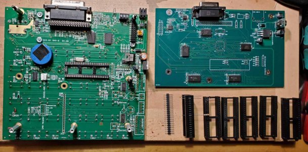
We'll see how it goes.So there's nothing COTS that let's me easily extend the socket pins from the original board to the new one. I used a machined high quality socket for the base ELS with the idea that maybe some time in the future I could insert these special rows of machined pins into the socket and into the companion board. But nothing is long enough to reach.Almost all the parts installed. The crystal is just sitting there while I wait for a 12Mhz part. That and a few others. Don't want to install the PIC32 until everything else has been tested. I've ordered 15mm stand offs and a few other parts to try and get the two to fit together.
Biggest mistake was the optical isolators; wrong foot print. But they aren't important for the first prototype. I had ordered 5 PC boards which was their minimum. They delivered 8 pieces.
View attachment 63978We'll see how it goes.

I'm on the forth print now. Holes have been enlarged to 1mm and the width also enlarged to allow more latitude in slicing. The last one with 0.8mm holes was still to tight for the wire but once I used a small PCB drill to clean it out it was fine. Then I broke the PCB drill in the second hole. Sigh...So there's nothing COTS that let's me easily extend the socket pins from the original board to the new one. I used a machined high quality socket for the base ELS with the idea that maybe some time in the future I could insert these special rows of machined pins into the socket and into the companion board. But nothing is long enough to reach.
After much thinking it suddenly hit me. I should 3D print the pin holder and use 24g solid wire for the pins. They are a perfect fit for the original socket and can be soldered into the board as a special header.
The slots along the sides are for some epoxy to just hold them in place. Bevel of 45 degrees so I don't have to use support filament. Printing will be done in 11 minutes. Now I wish I had some 24g solid wire. Time to head out to buy some.
View attachment 63991



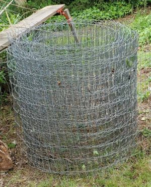
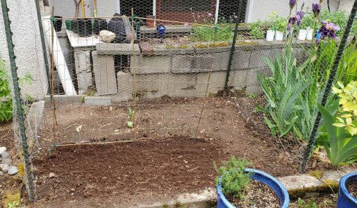
Thank you again for those. One must have hit a rock because it wouldn't go down as far as the other 3. And the chicken wire made it around the 3 sides perfectly.Those are some good looking stakes! 😉