• Scam Alert. Members are reminded to NOT send money to buy anything. Don't buy things remote and have it shipped - go get it yourself, pay in person, and take your equipment with you. Scammers have burned people on this forum. Urgency, secrecy, excuses, selling for friend, newish members, FUD, are RED FLAGS. A video conference call is not adequate assurance. Face to face interactions are required. Please report suspicions to the forum admins. Stay Safe - anyone can get scammed.
  • Several Regions have held meetups already, but others are being planned or are evaluating the interest. The Ontario GTA West area meetup is planned for Saturday April 26th at Greasemonkeys shop in Aylmer Ontario. If you are interested and haven’t signed up yet, click here! Arbutus has also explored interest in a Fraser Valley meetup but it seems members either missed his thread or had other plans. Let him know if you are interested in a meetup later in the year by posting here! Slowpoke is trying to pull together an Ottawa area meetup later this summer. No date has been selected yet, so let him know if you are interested here! We are not aware of any other meetups being planned this year. If you are interested in doing something in your area, let everyone know and make it happen! Meetups are a great way to make new machining friends and get hands on help in your area. Don’t be shy, sign up and come, or plan your own meetup!

JCDammeyer's 42 projects

Not ! You claim you always know where everything is. Organised chaos. :p

Nope, you are not reading me right. Yes, I do love organized chaos. That doesn't mean I like things hidden away in drawers where I can never find them. It means I prefer piles of stuff on surfaces. My chaotic organization is situational not everything has its place.
 
Almost one item ready to be taken of the list of 42 projects. I've wanted to consolidate the BoBs, MESA 7i92H and power supply to connect to the Raspberry Pi4 mounted to the back of the touch screen. Otherwise I have wires all over the place and stuff is loose. Just begging for magic smoke.

So today I installed all the stand-offs and mounted all the boards. There is room for a Pi with a CAN bus Hat in the middle if I decide not to use the small 10" touch screen. But it's progress.

Tomorrow I'll wire up the power supply and connect it all together. Ultimately this may run the CNC router or a small mill.
PanelStage1.jpg
 
There we go. All wired up. And clearly the power supply that both runs the Touch Screen and the Pi4 isn't up to snuff as the Pi4 is constantly complaining that the power supply voltage is too low.

The proper way of course to wire up the BoBs is not to generate the 5V for them from the 12V supply. Kind of defeats the whole idea of optically coupled and galvanic isolated I/O. So the right thing to do is probably get a 5A 5V supply and run the BoB's and Pi4 off that.

Notice the Blue Dongle. That's a CANUSB and there is code I've written for the LinuxCNC that sends and receives CANOpen messages to control the tool changer. That's one of the reasons I wanted this. So I can play around with all this.

PanelStage2.jpg


At this point I can set this aside until I finish a few other projects but at least now when I start it up again I don't have to look for cables, boards etc.

Many years ago (2005) I manufactured devices called WORMs. To program them I build an XYZ system that automatically programmed the panel. Used surplus stepper motors from PA. MACH3 for the CNC motion. Ultimately it was too slow and faster for me to just move the head by hand from board to board. Had I used good stepper motors and 5 TPI screws it would have been different. The whole XYZ system was disassembled and the pieces scattered here and there.

But now I have the infrastructure to build something similar again. But this time I would do the mechanics different.

Here's a very slow boring video if you want to lose just over 2 minutes of your life.
 
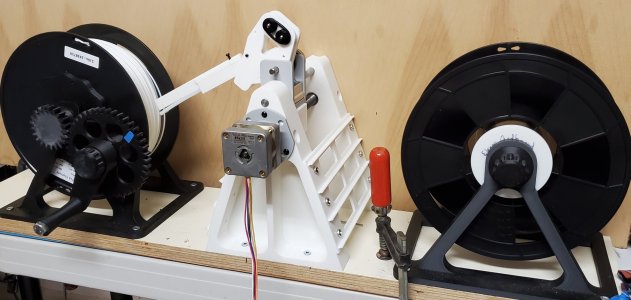
Progress on the filament rewinder project. My friend JoMac printed the first version that used a mechanical screw tracker to move the filament back and forth. It moved too far on each turn of the take up reel.

Now the Arduino code is pretty well done and there are 12 magnets in the take up hub so every 10th of a turn the stepper motor moves the guide over 0.175mm. That's been changed to 0.178mm because when I asked at the Matter3D open house yesterday they explained trial and error found 1.78mm filament spacing worked better than 1.75.

There are still issues. JoeMac is designing a new take up frame that is more robust. We're going to have to move the supply spool further away to make things less jumpy.
WinderProgress.jpg
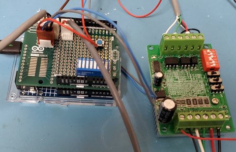
The Arduino UNO R4 is more than up to the job.
UNOR4-Controller.jpg
Also included is the schematic.
 

Attachments

My friend JoeMac has done the rake-up assembly in Fusion and exported it as a step file. I've added the hole for the filament to exit out the side if the take-up reel doesn't have a hole in the drum. This base is far sturdier and shouldn't flex when hand cranking this puppy. The original flexes enough when cranking that the laying of filament evenly doesn't happen after the first few layers. He's also added a clip in hold down for the one side to make pulling the heavy reel out easier.

I'm going to print this new base in PETG since it's also a bit stiffer although I'm tempted to use PLA Carbon Fibre. But we're still working on the idea of a motor mount.

1743987577711.png
 
We used it as the tender for this little puppy.

Hotfoot 24. A bit of lead in the bilge and a long daggerboard. We bought this in 1986 about a year or two after we did a cruise&learn 1 week sailing course out of Comox. Sailed it on Lake Wabamum for a few years. Then brought it back out to the coast and kept it at Van Isle Marina. The boat I think has more land miles than water miles. The guy who bought it towed it back to Lesser Slave Lake.

1745111527238.png
 
I have a new #42 project.
Almost exactly 20 years ago we decided repair the deck. When we bought the house in 1997 the deck was painted with a supposedly waterproof deck covering. The seller cleverly put his BBQ over top of the rotted plywood and inside the carport he had a small room there where he parked his garden tractor. So even looking in from the carport the damage wouldn't have been visible. Up till 2005 I had just nailed a piece of plywood over it to stop the leak.

I won't go into details as to the other reason for a major deck rebuild but anyway here's the first shot. Doesn't look too bad eh?
1745114775334.png


Well as things were taken apart it became obvious there was more hidden damage. You can see that dirt was also allowed right up to the frame.

1745114873322.png


Even used pressure treated lumber for the outer piece so that it would never rot again.

1745114965034.png


So when I was replacing some brackets that had rotted with 3D printed versions I discovered this:

1745115236077.png


Here's the other end on which the thinner 1x6 is also rotting. I'm guessing water dripped off the corner and wicked in between the joints and then just stayed wet. Never gets very sunny there due to the trees.

1745116097272.png

What to do?
 
Last edited:
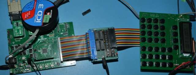
While sitting around trying to decide which of the 42 unfinished projects I should work on and looking through my tote boxes I kept having to move the prototype ELS Expansion project around. Yes it's in a box with the paperwork but just sitting there staring at me.


AdaptorBoard-7s.jpg

I took a look at the files and I have both Altium and the older Protel 99SE. The Altium harder to use and had weird pink boxes on some areas. The Protel 99SE was further along so I finished that. Photo and file dates were from 5 years ago.

Ordered the 4 layer boards today. Should be about a week or so. Then it can sit for another 5 years...
 

Attachments

While sitting around trying to decide which of the 42 unfinished projects I should work on and looking through my tote boxes I kept having to move the prototype ELS Expansion project around. Yes it's in a box with the paperwork but just sitting there staring at me.


View attachment 63688

I took a look at the files and I have both Altium and the older Protel 99SE. The Altium harder to use and had weird pink boxes on some areas. The Protel 99SE was further along so I finished that. Photo and file dates were from 5 years ago.

Ordered the 4 layer boards today. Should be about a week or so. Then it can sit for another 5 years...
Oh and it's purpose is to upgrade the ELS P18F series processor to a PIC32 that is specialized for motor control. That means it can handle high resolution quadrature encoders. I've also added a USB connector so theoretically I should be able to read a USB thumb drive for both upgrading firmware but maybe also accessing G-Code programs.

Finally brought out the Y axis step/dir signals to the original DB-25 and reworked where the PWM can go to the back of the ELS can plug directly into this MACH3 targeted Break Out Board with PWM to 10V signal conversion.

The idea has always been to create an ELS for a mill. The ability to set a BEGIN and END position and then tell the axis to move at a specific speed and RPM to that location. Great for the boring job of facing or edging.

1745448070308.png


But in reality with the inexpensive CNC controllers from the far east there's really no point other than to see if I can...
 
Oh and it's purpose is to upgrade the ELS P18F series processor to a PIC32 that is specialized for motor control. That means it can handle high resolution quadrature encoders. I've also added a USB connector so theoretically I should be able to read a USB thumb drive for both upgrading firmware but maybe also accessing G-Code programs.

Finally brought out the Y axis step/dir signals to the original DB-25 and reworked where the PWM can go to the back of the ELS can plug directly into this MACH3 targeted Break Out Board with PWM to 10V signal conversion.

The idea has always been to create an ELS for a mill. The ability to set a BEGIN and END position and then tell the axis to move at a specific speed and RPM to that location. Great for the boring job of facing or edging.

View attachment 63690

But in reality with the inexpensive CNC controllers from the far east there's really no point other than to see if I can...
Doesn't LinuxCNC have wizards or similar?
 
Doesn't LinuxCNC have wizards or similar?
Yes and no. Some people use command line programs. I think there are some graphical user interface tupe wizard type applications that produce G-Code. I believe the Tormach User Interface has that too.

The problem with LinuxCNC, MACH3/4 etc is one has to learn to work in the CNC world. The first thing I added to my mill was a DRO. On the quill and X/Y. Once I touched off I could then do bolt circles. I could move from say X=0.000 to X=2.000 using the DRO and the handles. Or if just facing or slotting using the power feed.
The end stops were adjustable so I could power feed X to a position and it would stop. Raise the quill. The feed could back off the switch and move back to the start. Then adjust Y or Z and use the power feed again.
Curves were done with the rotary table.

I wouldn't want to go back to that method since now I can whip up a G-Code program in the editor that does that pretty quickly. Wizards would be even nicer. I did take one of the Command Line programs for boring a whole and rewrite it in Lazarus (Object Pascal write once compile anywhere). I believe this screenshot was from Raspberry Pi with LinuxCNC.

1745449371336.png


I think there was a bug in the original C program with I/J resulting in LinuxCNC complaining about end point not equal to start point or something sill. Never went further with this.
1745449700657.png

With R commands I think it did work. It can also work in mm. Screen shot below runs on my PC.

1745449495808.png


Could also be metric of course with imperial or metric tools.
1745449613466.png
 
The C programs were written by Jon Elson. Quite a few actually.
1745450587086.png


Here's an example of hole drilling.
N10 G61.1 M03 S2000
N20 G01 Z0.5 F45
N30 G01 F45 X3.0000 Y5.0000
N40 Z0.1000
N50 Z-0.5000 F12.00
N60 Z0.1000 F45.00
N70 G01 F45 X3.5000 Y5.5000
N80 Z0.1000
N90 Z-0.5000 F12.00
N100 Z0.1000 F45.00
N110 G01 F45 X4.0000 Y6.0000
N120 Z0.1000
N130 Z-0.5000 F12.00
N140 Z0.1000 F45.00
N150 M02
Pretty simple actually. Move to a position 0.1" above the work. Drill a 0.5" hole at a feed rate of 12IPM. Back up to 0.1" above. Move to next position. Rinse and repeat.
 
Back
Top