For engraving I always use a 2-flute, 60 degree V-bit.With what type of cutter?
-
Scam Alert. Members are reminded to NOT send money to buy anything. Don't buy things remote and have it shipped - go get it yourself, pay in person, and take your equipment with you. Scammers have burned people on this forum. Urgency, secrecy, excuses, selling for friend, newish members, FUD, are RED FLAGS. A video conference call is not adequate assurance. Face to face interactions are required. Please report suspicions to the forum admins. Stay Safe - anyone can get scammed.
-
Several Regions have held meetups already, but others are being planned or are evaluating the interest. The Calgary Area Meetup is set for Saturday July 12th at 10am. The signup thread is here! Arbutus has also explored interest in a Fraser Valley meetup but it seems members either missed his thread or had other plans. Let him know if you are interested in a meetup later in the year by posting here! Slowpoke is trying to pull together an Ottawa area meetup later this summer. No date has been selected yet, so let him know if you are interested here! We are not aware of any other meetups being planned this year. If you are interested in doing something in your area, let everyone know and make it happen! Meetups are a great way to make new machining friends and get hands on help in your area. Don’t be shy, sign up and come, or plan your own meetup!
You are using an out of date browser. It may not display this or other websites correctly.
You should upgrade or use an alternative browser.
You should upgrade or use an alternative browser.
JCDammeyer's 42 projects
- Thread starter jcdammeyer
- Start date
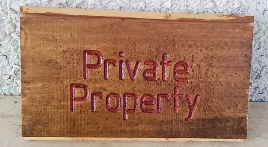
This one was first engraved with the ¼” round router bit through clear packing tape. Then sprayed with red paint. Once the paint was dry the grooves were filled with clear water based varathane. This morning, packing tape removed and run over the jointer to clean up surface and any red areas that bled through. Finally a coat of combination stain/varathane.
Doesn’t look too bad. I like the idea of sealer before even before doing the red. Might try that next using shellac. Then after red dry and tape removed shellac everything. Might not need to use the jointer.
John
Doesn’t look too bad. I like the idea of sealer before even before doing the red. Might try that next using shellac. Then after red dry and tape removed shellac everything. Might not need to use the jointer.
John
Attachments
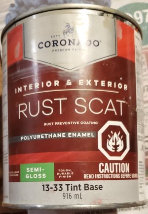
This is the paint I used a few years ago, colour matched to the mill. It's what I used to paint the table covers which now more than 24 hours later still hasn't really dried hard. It's sticky and will take a fingerprint impression.
Does Polyurethane Enamel age in a way that it won't harden?
Does Polyurethane Enamel age in a way that it won't harden?
Attachments
slow-poke
Ultra Member
From what I have read many of the polyurethane paints cure slowly.This is the paint I used a few years ago, colour matched to the mill. It's what I used to paint the table covers which now more than 24 hours later still hasn't really dried hard. It's sticky and will take a fingerprint impression.
Does Polyurethane Enamel age in a way that it won't harden?
I decided to try this one, it's supposed to cure quickly, 15 minutes to the touch. I will let you know if I ever find some time to use it.
High Performance Command | Benjamin Moore
Command® is an extremely durable single-component, multi-substrate solution that helps you save time and tackle multiple jobs with confidence.
 www.benjaminmoore.com

Does Polyurethane Enamel age in a way that it won't harden?
I believe so. As you probably know, it doesn't dry, it cures. That curing is affected by the presence of oxygen and takes longer as the paint gets older. So if the paint can was ever opened, oxygen will get inside and start affecting the paint's long term stability.
I used to use polyurethane paints for it's durable finish. my typical brush on cure times ranged from 1 week to 2 weeks. moisture in the air seems to slow curing. Don't apply heat to hasten the process: it forms a crust that prevents full depth curing for months. You know how I know!!
Since I'm watching paint dry I thought I'd leave the covers out of the way and get after another one of the 42 projects.
When I switched over to the AC Servo from the Brushed DC Servo I needed a new motor mount with a smaller centre hole and motor mounting holes. At the time I grabbed a piece of scrap with full intentions of eventually casting a new plate the right thickness (1/2" instead of 3/8"). The scrap plate was about an inch too wide but it worked and I could continue.
Well 4 years have gone by and I'm printing new covers because the existing one cracked so I thought, time to narrow down the plate so the 3D printed cover will fit.
This demonstrates why sometimes a CNC conversion, that still makes it possible to install the original handle for manual movement, is really handy. Although I guess I could also drill a hole in the face of the driven pulley and install a handle when needed.

Andway, after sawing off the waste part on the bandsaw (a little too close to the line) I clamped it in the vice and used the X axis as a simple manual mill power feed with G-Code line G1 X7.7 F5
The depth of cut was tweaking in with the MPG but I could have also used the quill.

Now just to print the third piece after I tweak a few dimensions plus design a cover for the turning bolt.

Anyway. CNC is operational again.
When I switched over to the AC Servo from the Brushed DC Servo I needed a new motor mount with a smaller centre hole and motor mounting holes. At the time I grabbed a piece of scrap with full intentions of eventually casting a new plate the right thickness (1/2" instead of 3/8"). The scrap plate was about an inch too wide but it worked and I could continue.
Well 4 years have gone by and I'm printing new covers because the existing one cracked so I thought, time to narrow down the plate so the 3D printed cover will fit.
This demonstrates why sometimes a CNC conversion, that still makes it possible to install the original handle for manual movement, is really handy. Although I guess I could also drill a hole in the face of the driven pulley and install a handle when needed.
Andway, after sawing off the waste part on the bandsaw (a little too close to the line) I clamped it in the vice and used the X axis as a simple manual mill power feed with G-Code line G1 X7.7 F5
The depth of cut was tweaking in with the MPG but I could have also used the quill.
Now just to print the third piece after I tweak a few dimensions plus design a cover for the turning bolt.
Anyway. CNC is operational again.
There we go. The Y Axis parts are all printed. Bottom two are glued. Time to sand and prime.

The Z axis covers on the left were printed over 4 years ago on the old 3D printer. Quality from the Bambu is so much nicer.
The Z axis covers on the left were printed over 4 years ago on the old 3D printer. Quality from the Bambu is so much nicer.
So I took another look at the paint can. One to two hours for tacky. Twenty four hours for recoat. Ten days for full cure. It's been about 6 days and the painted covers are now hard enough to handle without leaving fingerprints or feeling sticky.I used to use polyurethane paints for it's durable finish. my typical brush on cure times ranged from 1 week to 2 weeks. moisture in the air seems to slow curing. Don't apply heat to hasten the process: it forms a crust that prevents full depth curing for months. You know how I know!!
I also 3D printed some curved retainers that fit around the cable but the cable can still be snapped out without undoing the 3mm screws that are screwed into heat set brass inserts.

Meanwhile I now get to watch paint dry on the Y axis covers. Guess I should have added filler in the glued joint on the big panel.

Next. Finish the Z axis cover and get started on an X axis cover.
Oh and get back to figuring out why the tool sensor doesn't properly set the correct tool length offset when measuring tools.
And then there's the stepper motor c/w planetary reduction gear draw bar control. For that I have to cast new parts so the real project is to get back to casting since the pneumatic version doesn't fit. I need to cast and machine the green bits.

So many projects...
Here we go. Knee pulley cover printed with tree support. Printer was tall enough to handle the two sections that the old printer wasn't. I've widened the pulley clearance because the existing one would occasionally rub with squeaking noise.

Thanks. What I'm finding too is how much this is improving my CAD techniques. The original parts from 4 years ago (or maybe even longer) used a lot of absolute values. I've had to go through and make many of the parametric so if I change the wall thickness from 2mm to 3mm that other dimensions change appropriately.Look great John. Its actually amazing how much 3d printing and machining work together.
For example instead of dimension D72 being 3mm it's changed to D72 is D58 where D58 is the wall thickness.
The original was printed on my first small 3D printer in 3 parts. Now the top section is a single part and even so I made a boo-boo. Not a big deal but it was an "awe crap!" moment.
Now just to print new brackets to screw the bottom to the metal plate and holes in the sides of the top piece to connect to the other bottom plate.

Edit: Oh and the paint on the Y Axis part is still tacky. I'll wait the requisite 10 days before I muck with it.
Next step was to disassemble the knee bearing and motor mount since there wasn't enough room to try to hand drill and tap holes into the castings. The scary part was if I screw something up then I might have to cast and machine a new part. Since I no longer had CNC Z motion it seemed easier to do this on the drill press as the vise isn't fixed although mill and using the quill would have worked too.

Now to put it back together. May well hold off painting for a while to make sure the Y axis does properly cure.
Now to put it back together. May well hold off painting for a while to make sure the Y axis does properly cure.
It looks really nice and very solid. Also no rubbing as I made a new front cover with a larger cavity.

Looks great. I like the bulge. Also love the amount of screws. When it’s painted with nice cover screws adds that extra little touch.It looks really nice and very solid. Also no rubbing as I made a new front cover with a larger cavity.
View attachment 68850
It doesn't really need them but the printed 3.3mm hole accepts the 4mm screw without needing to tap it first. Just forms the threads well enough. Now if I strip one I have extra places.Looks great. I like the bulge. Also love the amount of screws. When it’s painted with nice cover screws adds that extra little touch.
The bottom plate actually hooks under the overhang. The overhang is there so any oil or coolant drips off rather than into.
I've got to check whether there is some sort of additive that can be added to the paint to bring the curing time back to spec.
Meanwhile I've been investigating an DFU2505 ball screw for the X axis. Ball screws are also on the 42 projects list.
You will love ball screws!Meanwhile I've been investigating an DFU2505 ball screw for the X axis. Ball screws are also on the 42 projects list.
I have them on the CNC router XY. Not the Z yet.You will love ball screws!
140mower
Don
Oh my!!!! That sounds painful. 😱You will love ball screws!
The paint has cured enough that I can at least put the covers on the Y axis. The X axis is still a work in progress. Rather than print 42 renditions of the bottom part of the X axis cover I think it will be easier just to mill the motor mount casting to the correct dimensions. Leaving it as cast was fine but now it's too wide to match the back casting.
