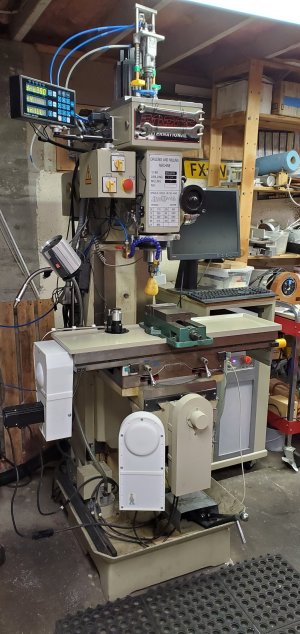
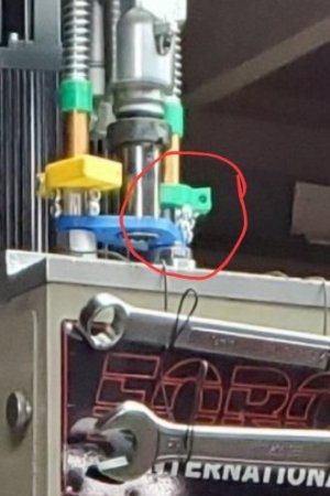
Nope. Buy find Waldo in this one...What? No partridge?
-
Scam Alert. Members are reminded to NOT send money to buy anything. Don't buy things remote and have it shipped - go get it yourself, pay in person, and take your equipment with you. Scammers have burned people on this forum. Urgency, secrecy, excuses, selling for friend, newish members, FUD, are RED FLAGS. A video conference call is not adequate assurance. Face to face interactions are required. Please report suspicions to the forum admins. Stay Safe - anyone can get scammed.
-
Several Regions have held meetups already, but others are being planned or are evaluating the interest. The Calgary Area Meetup is set for Saturday July 12th at 10am. The signup thread is here! Arbutus has also explored interest in a Fraser Valley meetup but it seems members either missed his thread or had other plans. Let him know if you are interested in a meetup later in the year by posting here! Slowpoke is trying to pull together an Ottawa area meetup later this summer. No date has been selected yet, so let him know if you are interested here! We are not aware of any other meetups being planned this year. If you are interested in doing something in your area, let everyone know and make it happen! Meetups are a great way to make new machining friends and get hands on help in your area. Don’t be shy, sign up and come, or plan your own meetup!
You are using an out of date browser. It may not display this or other websites correctly.
You should upgrade or use an alternative browser.
You should upgrade or use an alternative browser.
JCDammeyer's 42 projects
- Thread starter jcdammeyer
- Start date
I don't like stepper motors[; their noise and lost torque at higher RPM. I had DC Brushed Servos with UHU HP controllers that worked really well until I noticed lost motion on X. The X motor also never got as hot as the Y motor. Final investigation revealed the X motor had twice the resistance in the windings compared to the Y motor. Likely a 180VDC motor and not a 90VDC motor but labelled incorrectly. Automation Technologies wouldn't replace it as it was already many years old before I ever installed it. Cost of a replacement 90V motor was more than ordering from Bergerda in China.Looking good!
My new lathe X-axis cover is "boxy" in comparison to yours.
I decided to go direct drive for X & Y on the mill.
Servo power, 400W, or smaller?
Backlash on the Z axis?
Replacing the 1100 oz-in stepper on the knee with a 750W motor also upped my Z speed to a scary 120 IPM from max 25 IPM. And it's so quiet now.
Oh yes and 400W on X and Y with 3:1 and 4:1 ratio.
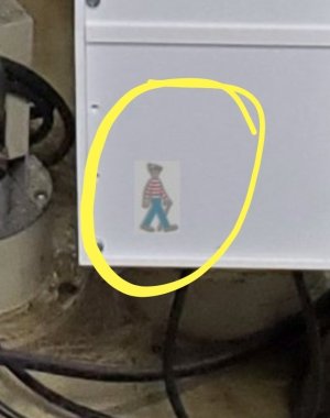
Taa Daa! I probably should have cut him out of the white background and hidden him better.
Taa Daa! I probably should have cut him out of the white background and hidden him better.
It was difficult enough. As it is, I had to download your photo, zoom in, and then do a raster search. I wasn't even really sure he was there.
We have the youngest bunch of grandkids for the weekend so I can't do much beyond looking for Waldo anyway.
Thanks for the diversion.
slow-poke
Ultra Member
I'm with you on the servo vs. Stepper, both my mill and lathe are 100% ac servo and they have no problem moving at crazy speeds near silently. Drives are powered by 220-240Vac, I'm using Yaskawa for the lathe, and they are very easy to tune.I don't like stepper motors[; their noise and lost torque at higher RPM. I had DC Brushed Servos with UHU HP controllers that worked really well until I noticed lost motion on X. The X motor also never got as hot as the Y motor. Final investigation revealed the X motor had twice the resistance in the windings compared to the Y motor. Likely a 180VDC motor and not a 90VDC motor but labelled incorrectly. Automation Technologies wouldn't replace it as it was already many years old before I ever installed it. Cost of a replacement 90V motor was more than ordering from Bergerda in China.
Replacing the 1100 oz-in stepper on the knee with a 750W motor also upped my Z speed to a scary 120 IPM from max 25 IPM. And it's so quiet now.
Oh yes and 400W on X and Y with 3:1 and 4:1 ratio.
The DC servos were great and worked well. Or so I thought. The DRO reported that a return to a specific position started drifting. Yet the driver never reported missing steps. As in move say 2000 steps and it didn't move 2000 steps according to the DRO yet the drive didn't report the issue.I'm with you on the servo vs. Stepper, both my mill and lathe are 100% ac servo and they have no problem moving at crazy speeds near silently. Drives are powered by 220-240Vac, I'm using Yaskawa for the lathe, and they are very easy to tune.
If was only after a milling operation had a new cut at a deeper depth wasn't in line with the previous ones. Swapping the controller didn't help while swapping the motors fixed the problem. That's when I noticed the working motor got hotter because of course to hold position a certain amount of current had to flow through the windings. Really too bad as I bought 4 of the bare PC boards and parts and assembled and tested two of them. The other two are almost complete.
slow-poke
Ultra Member
I finally found some time to paint my Utilathe.From what I have read many of the polyurethane paints cure slowly.
I decided to try this one, it's supposed to cure quickly, 15 minutes to the touch. I will let you know if I ever find some time to use it.
View attachment 68606High Performance Command | Benjamin Moore
Command® is an extremely durable single-component, multi-substrate solution that helps you save time and tackle multiple jobs with confidence.www.benjaminmoore.com
Benjamin Moore has yet to disappoint, drys to the touch in 15-20 minutes, apparently cures hard enough for forklift traffic in 24 hours. Goes on like typical B.M. I can't comment on durability yet, however first impressions are excellent.
B.M. Might be a bit more expensive, but typically saves you a bunch of time when applying it.
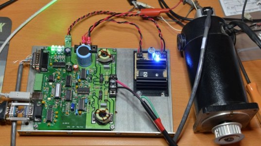
Don't think I ever posted photos of the power supply I built for the DC Servos. Although the motors were rated for 90VDC the supply was closer to 115VDC.
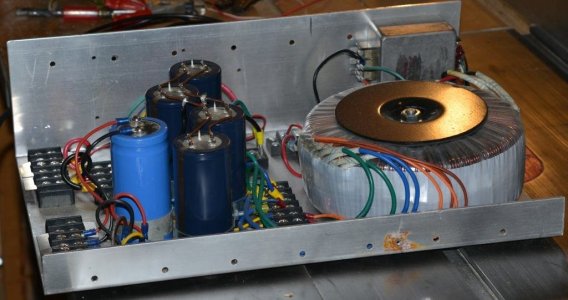
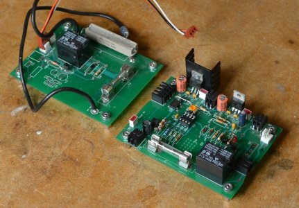
To avoid blowing a breaker or fuse when it powered up I had a circuit that inserted a power resistor into the primary circuit to reduce the inrush current. That's the board on the left. After a few seconds the relay would kick in and allow full voltage into the windings.
The second board served as an over voltage clamp so when the DC servos decelerated and generated voltage it would clamp anything over 115VDC. And when power was shut off the relay would connect that same load dump resistor across the capacitors reducing the lethal DC voltage to 0 in a few seconds.
Now the only thing this supply is used for is the harmonic drive 4th axis. Which isn't complete yet and it could use a 180VDC power supply.
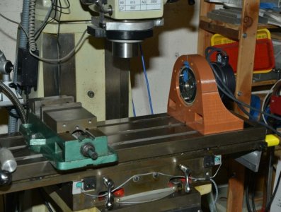
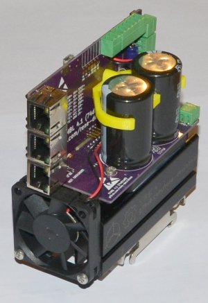
It's an AC Servo and run with a STMBL Servo drive kit.
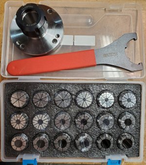
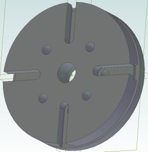
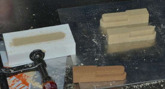
Project #42 is casting the frame along with casting the face plate so I can mount the ER32 chuck.

To avoid blowing a breaker or fuse when it powered up I had a circuit that inserted a power resistor into the primary circuit to reduce the inrush current. That's the board on the left. After a few seconds the relay would kick in and allow full voltage into the windings.
The second board served as an over voltage clamp so when the DC servos decelerated and generated voltage it would clamp anything over 115VDC. And when power was shut off the relay would connect that same load dump resistor across the capacitors reducing the lethal DC voltage to 0 in a few seconds.

Now the only thing this supply is used for is the harmonic drive 4th axis. Which isn't complete yet and it could use a 180VDC power supply.

It's an AC Servo and run with a STMBL Servo drive kit.

Project #42 is casting the frame along with casting the face plate so I can mount the ER32 chuck.
Way back when I first bought the paint it dried as per the can label. Now it's really old and takes forever to cure.I finally found some time to paint my Utilathe.
Benjamin Moore has yet to disappoint, drys to the touch in 15-20 minutes, apparently cures hard enough for forklift traffic in 24 hours. Goes on like typical B.M. I can't comment on durability yet, however first impressions are excellent.
B.M. Might be a bit more expensive, but typically saves you a bunch of time when applying it.
slow-poke
Ultra Member
So if I follow the alarm report when servo fails close-loop is not working?The DC servos were great and worked well. Or so I thought. The DRO reported that a return to a specific position started drifting. Yet the driver never reported missing steps. As in move say 2000 steps and it didn't move 2000 steps according to the DRO yet the drive didn't report the issue.
If was only after a milling operation had a new cut at a deeper depth wasn't in line with the previous ones. Swapping the controller didn't help while swapping the motors fixed the problem. That's when I noticed the working motor got hotter because of course to hold position a certain amount of current had to flow through the windings. Really too bad as I bought 4 of the bare PC boards and parts and assembled and tested two of them. The other two are almost complete.
View attachment 69052
Who's board is that?
Or is the board generating the alarm and the CNC control software ignoring it?
It's an HP-UHU DC Servo Drive board.So if I follow the alarm report when servo fails close-loop is not working?
Who's board is that?
Or is the board generating the alarm and the CNC control software ignoring it?
The original from Germany used an ATMEL processor that the designer supplied for a very low cost. The circuit board was open source. I ordered the first one from a guy in India along with a kit of parts. This was back in 2008.
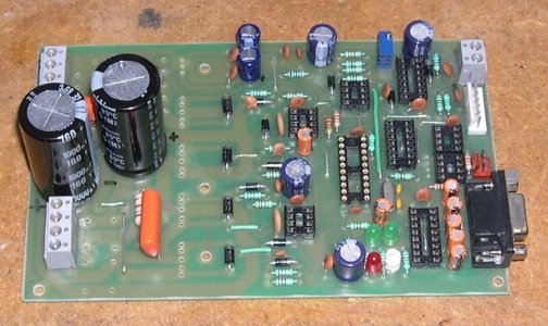
It worked well but was limited to about 48V.
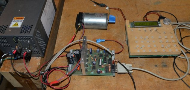
Then someone else designed what was the HP-UHU which upgraded the circuit to work with high voltage drives. Then Henrik Olsson in Sweden wrote new software for a Microchip PIC processor to better deal with faults etc. The little board plugs in place of the ATMEL processor.
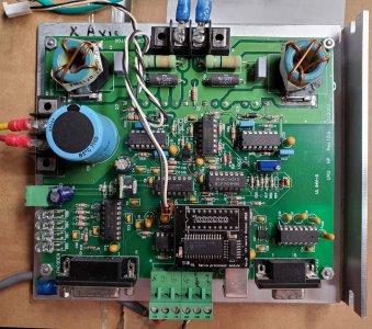
The odd thing is the encoder never reported a lost position. Almost as if the pulleys were slipping but they are keyed. The problem was found to move with the motor to the Y axis so couldn't have been mechanical either.
To this day I have no idea what happened or why other than motor resistance differences. Why neither the ATMEL UHU processor or the Henrik's PIC reported a problem I do not know.
I'd already switched from US Digital Encoders which Henrik said were unreliable.
At that point switching to COTS AC servos was a better solution even if more expensive rather than pouring good money after bad. One day I may do something about this but not right now.
Productive evening yesterday. First file off the small rivets and then drill out and tap to 4mm the 4 rivet holes. Really don't like hand drilling into cast iron but I was successful.
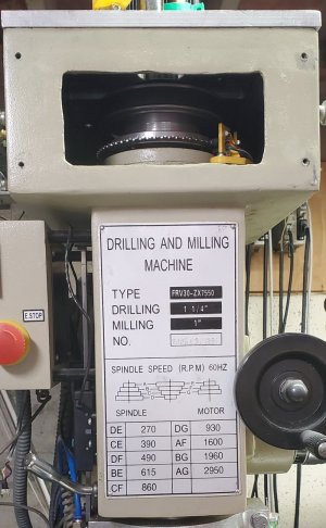
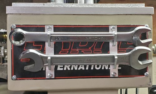
Since the lower part of the hole was too far down for my wrench clips I cut a piece of 1/4" scrap plywood from the "it will be useful someday" bin and also inserted brass 4mm nuts. Each of which had to be tapped again because the Chinese tolerance compared to the screws I had made them too tight. That and center punching and drilling one hole in the wrong place. I blame that on my new glasses since there was clearly a cross hair mark beside the wrong hole.
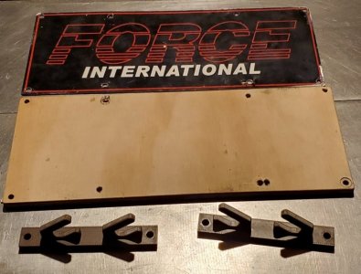
And then installed. When I paint everything the plywood will also get a coat so the edges don't look like plywood. A lot of work just to hang two wrenches.
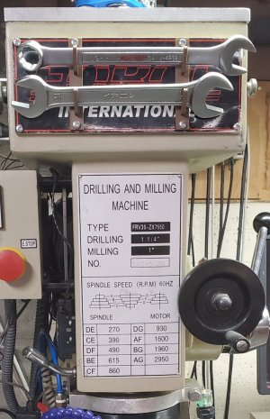
Cross off one project from the list of 42. Count how many projects left... still 42... sheesh...

Since the lower part of the hole was too far down for my wrench clips I cut a piece of 1/4" scrap plywood from the "it will be useful someday" bin and also inserted brass 4mm nuts. Each of which had to be tapped again because the Chinese tolerance compared to the screws I had made them too tight. That and center punching and drilling one hole in the wrong place. I blame that on my new glasses since there was clearly a cross hair mark beside the wrong hole.

And then installed. When I paint everything the plywood will also get a coat so the edges don't look like plywood. A lot of work just to hang two wrenches.

Cross off one project from the list of 42. Count how many projects left... still 42... sheesh...
No such thing as a hole in the wrong place. It must be a ventilation shaft.That and center punching and drilling one hole in the wrong place.
So the wrench hangers are now permanently mounted.
Why two wrenches John? And why not a rachet wrench?
I only have one wrench on my mill - a 3/4" open end rachet wrench. The rachet make turning more than a few degrees easy. The direction is indicated by where the jaws point. It operates my drawbar and my vise.
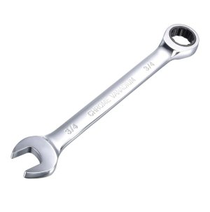
The open end wrench is for two different size bolts on the mill.Why two wrenches John? And why not a rachet wrench?
I only have one wrench on my mill - a 3/4" open end rachet wrench. The rachet make turning more than a few degrees easy. The direction is indicated by where the jaws point. It operates my drawbar and my vise.
View attachment 69137
I don't have a spindle lock so I use what Rick Sparber coined as a "WUT". He had an article in Practical Machinist many years ago. The WUT is the size of the existing open end wrench used on the rest of the mill. The 19mm is the size of my draw bar nut.
BTW, his site is a goldmine of interesting articles.
BTW, on the list of 42 projects is pulling the spindle and boring a slight recess to hold the WUT centered.

