• Scam Alert. Members are reminded to NOT send money to buy anything. Don't buy things remote and have it shipped - go get it yourself, pay in person, and take your equipment with you. Scammers have burned people on this forum. Urgency, secrecy, excuses, selling for friend, newish members, FUD, are RED FLAGS. A video conference call is not adequate assurance. Face to face interactions are required. Please report suspicions to the forum admins. Stay Safe - anyone can get scammed.

JCDammeyer's 42 projects

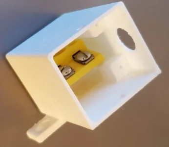
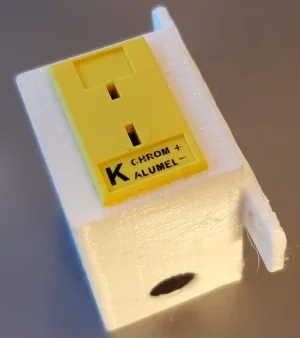
Not sure why the 3D print quality is so poor here. I must have mucked up one of my settings when I was trying stuff and now...

I think I my reprint and also add some holes on the side to access the screw heads. The panel connector is a nice tight press fit so should probably be alright.
 

Attachments

  • WhiteBoxBottom.webp
    WhiteBoxBottom.webp
    40.8 KB · Views: 2
  • WhiteBoxTop.webp
    WhiteBoxTop.webp
    27.3 KB · Views: 4
Definitely LOL...
I made the box a bit deeper and removed the mounting screw extrusion so there would be room to push in the mounting clip. Although unless I put screw driver holes in the side to access the mounting screws it's a one way trip with the metal hold down clip.

View attachment 50869

View attachment 50870

View attachment 50871
Accessibility is important.
Working on projects with Millwrights for decades makes assembly and service KEY considerations when designing components.
I always hated those Right Angle screwdrivers !!
 
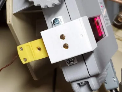
So here we are. One problem with reassembly is the connector for the 3 single LEDs was being intermittent and so the top one wouldn't light. Spent some time fixing that on final assembly.

But the Thermocouple interface box is now done and has a K Type connector on the back side. I think this was print #4 has I had to deal with cables and connectors that had trouble fitting inside that tiny space. Even the K Type wire was stiff and hard to route. Just all sorts of shortcuts I did earlier that came back to bite me.

Had to make the box 2mm longer to make room for the ribbon cable coming off the connector. That meant the two large mounting screws were now a slight interference fit but I forced them in anyway.

It would have been nice if I'd still had the same grey but so it goes. I should make a small snap in cover for the screw access holes just to make it pretty.
 

Attachments

  • ThermocoupleINterfaceBox.webp
    ThermocoupleINterfaceBox.webp
    44 KB · Views: 0
Onward with another project on the list of 42 to complete. One has to look at the one that the late Rupert Wenig from Camrose built. The linear Y-Axis rails are supported with castings to minimize deflection. He made a bunch of smaller pieces to make machining them easy for a flat fit on his mill. Then assembled them together to support the rail.
Ruperts2.jpg
By itself my solid rod flexes 0.035" in the middle from the weight of the Gantry. That matches the calculations that Chris MacKay did for me way back. He came up with the need for a 5" high gantry support structure to prevent that amount of flex. Important if I wanted to mill PC boards.

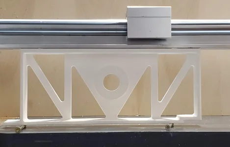
So with help from another Mech Eng I drew up my own supports. Set up as a split pattern with the second half currently being 3D printed. As I have to make 8 total I'll do the usual primer, bondo, paint to make them come out of the sand easily. Really wondering if doing a weldment and taking that to a place that can surface grind the 45" length flat would be less work. Probably but way more expensive for metal and labour.

SupportAssemblyDrawing.jpg

Here's one half of the pattern with one of the two linear bearings.
Y_Axis_LinearRailSupport.jpg

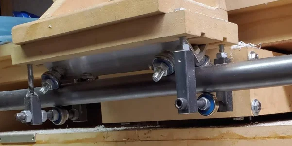
Here's what it's replacing.
JGRO-SkateBearings.jpg

Edit: Correct some bad grammar.
 
Last edited:
It is all about having enough ‘Section Modulus’ to support the Load.

I once designed 10x6x3/8” tube with 1x6” Flatbar stitch welded to the top and bottom of the rectangular tube. It provided enough material to support a 2500# load at the mid span location and limit deflection to .020”.

Key was the 1x6” Flatbar because they were welded at the top and bottom of the tube which resulted in more material being farthest away from the Neutral Axis (Result: More stiffness in for the amount of steel in the fabricated Beam).
 
Onward with another project on the list of 42 to complete. One has to look at the one that the late Rupert Wenig from Camrose built. The linear Y-Axis rails are supported with castings to minimize deflection. He made a bunch of smaller pieces to make machining them easy for a flat fit on his mill. Then assembled them together to support the rail.
View attachment 50964
By itself my solid rod flexes 0.035" in the middle from the weight of the Gantry. That matches the calculations that Chris MacKay did for me way back. He came up with the need for a 5" high gantry support structure to prevent that amount of flex. Important if I wanted to mill PC boards.

So with help from another Mech Eng I drew up my own supports. Set up as a split pattern with the second half currently being 3D printed. As I have to make 8 total I'll do the usual primer, bondo, paint to make them come out of the sand easily. Really wondering if doing a weldment and taking that to a place that can surface grind the 45" length flat would be less work. Probably but way more expensive for metal and labour.

View attachment 50965

Here's one half of the pattern with one of the two linear bearings.
View attachment 50966

Here's what it's replacing.
View attachment 50967

Edit: Correct some bad grammar.
You might know something I don't (well lots actually) but I would think you'd be hard pressed to find a surface grinder that size around here.
 
Doesn't have to be surface grind flat. Just flat for bolting down the rail. Rupert did his in small sections. My mill can with the proper jigging likely make each piece the exact same height.
Doing a big welding with the associated heat warping that I'm sure I'd introduce could probably be flattened at one of the larger engine shops that do large boat engines. But the cost...

I've primed both pieces with primer/filler. Now the labour intensive sanding down to find the dips and valleys from 3D printing. Then filler, more primer.

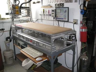
I'm not in a hurry. The pictures of the initial CNC router setup are dated 2010 but I've had the linear bearing rails for only 10 years so it's time to do something with them...
Only 10 years, I have shirts older then that. The machining after welding may not ever catch up to the warping. Sounds like the mill to make same height maybe best.
 
I have lots of time. Still about 8 other finished patterns to print before I get to this. But the idea is to whittle away at each old project for about 42 minutes at a time...

Here's one of the 1.5 degree tapered faces of the 3D print. First layer of primer sanded down. If you zoom in you might be able to see there are still some 3D printed grooves that need filler but the next coat will probably do that. Once painted with glossy paint it will leave a very smooth sand surface and pull out of the green sand without tearing.
 

Attachments

  • 3DPrintSanded.webp
    3DPrintSanded.webp
    48.3 KB · Views: 3
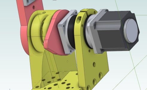
Between waiting for paint to dry and being pulled into updating some clients projects I decided to get back to the Robot arm project. (#42 on the list).

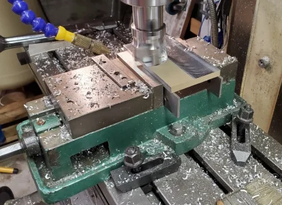
One of the pieces is 0.3125" thick and I had some salvaged 0.375" powder coated stuff. So time to remove the paint.
RemovingPaint.webp

I've also discovered that either the vise is off or sitting on something. The thickness from one end to the other is different by about 0.002" over 7".
 
If it's powder coated on both sides it could be just the thickness of the powder coat isn't consistent.
Ah. Hadn't thought of that. I tried to set the flattest part on the parallels first. Even then the first pass showed the top part of the metal wasn't exactly flat. Could be my vise work too although the dead blow hammer was used to seat it into the slightly tightened jaws. The parallels didn't move.

I still need to make it a bit thinner yet so I'll bring out the dial indicator and check the vise registration surface relative to the table. I guess I really should learn how to properly use my mill.:rolleyes:
 
Time to go down the checklist.
- squareness
- parallel
- play in the mill
- achievable accuracy
- is it really required (do I need it that precise ?)

Do not take the FUN out of your hobby !!
 
Success. After almost 3 days of going through the code etc. I finally figured out what I had forgotten from a year ago. My documentation to myself needs some major improvement. Anyway. Now I can put a drill bit and have the system see that it has a zero length in the tool table so it goes out to the tool setter and now gets the length right.

After that it was easy to drill a hole, mount a 1/4-20 tap in another collet tool # 6 also with 0 length and watch it go to the tool setter, grab the length and then over to the previously drilled hole and at 100 RPM away we go.

1725673242221.png


This is the first hold down. I'll do 3 more on the outside area that will be removed. Or I could just use clamps. But the tapping is so much fun.
1725673345267.png


The 4 holes are 3.3mm diameter and so I will also put in some threaded holes in the back plate to hold it place during the final trimming shown in the tool path below.

1725673432681.png
 
Well aside from one broken 2.5mm drill bit and one broken 3mm tap and accidentally changing the X=0.000 location the result is passable but really a piece of crap.

This J1 Tension Plate is designed to compress the two tapered bearings and connect the motor drive along with a tab to hit a limit switch. Here's the CAD drawing of it.

J1TensionRing-0.jpg

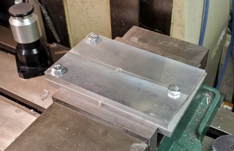
Starting with a sacrificial mounting plate and the target part drilled in 3 points and bolted down. Part hold down hole also in place.

J1TensionRing-1.jpg

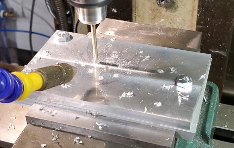
Now I drilled the 3.2 and 3.5mm holes and counter sunk them.

J1TensionRing-2.jpg

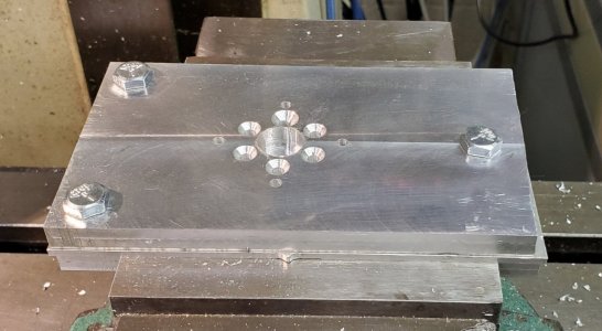
First mistake was the initial depth of the counter sink was too deep. I had actually stopped it there and started cranking it down manually when I realized the target hole from the CAD drawing was way wrong. Edited the G-Code and set new depth for all 6 holes and then ran it again. Much better.

J1TensionRing-3.jpg

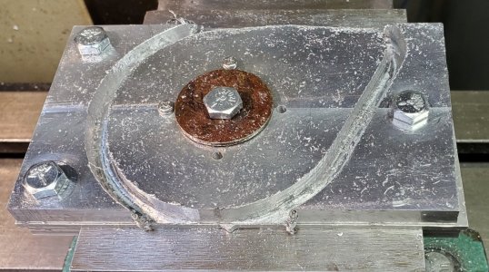
I had also spiral bored out the middle hole which is a clearance fit over a 14mm shaft so nothing special but somehow both my zero and depth were off. Didn't quite cut into the mounting place. And worse is in readjusting the Z=0.000 using the drag paper under the cutter approach, I accidentally zero'd X. At that point it was a bear to get it recentered since my original reference point was off and I didn't think to use the probe on the hole. Sigh.

Next step Profile the outside. Clamp down, Z=0.000 means it should now cut into the bottom plate by a teensy bit. Not...
J1TensionRing-4.jpg

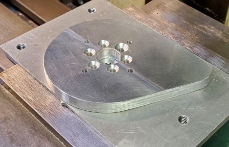
After all is said and done and some file work it's usable but I'm not happy.
J1TensionRing-5.jpg
The backlash and positioning really didn't make for the greatest cut. A depth of 0.1" per pass and 5 IPM with a 1/4" two flute end mill. I likely should have left 0.010" and then done a single pass around with a 1/4" four flute end mill.

I may have to restart project #42 and add ball screws to the mill. The backlash is killing me.
 
Well aside from one broken 2.5mm drill bit and one broken 3mm tap and accidentally changing the X=0.000 location the result is passable but really a piece of crap.

This J1 Tension Plate is designed to compress the two tapered bearings and connect the motor drive along with a tab to hit a limit switch. Here's the CAD drawing of it.

View attachment 51503

Starting with a sacrificial mounting plate and the target part drilled in 3 points and bolted down. Part hold down hole also in place.

View attachment 51498

Now I drilled the 3.2 and 3.5mm holes and counter sunk them.

View attachment 51499

First mistake was the initial depth of the counter sink was too deep. I had actually stopped it there and started cranking it down manually when I realized the target hole from the CAD drawing was way wrong. Edited the G-Code and set new depth for all 6 holes and then ran it again. Much better.

View attachment 51500

I had also spiral bored out the middle hole which is a clearance fit over a 14mm shaft so nothing special but somehow both my zero and depth were off. Didn't quite cut into the mounting place. And worse is in readjusting the Z=0.000 using the drag paper under the cutter approach, I accidentally zero'd X. At that point it was a bear to get it recentered since my original reference point was off and I didn't think to use the probe on the hole. Sigh.

Next step Profile the outside. Clamp down, Z=0.000 means it should now cut into the bottom plate by a teensy bit. Not...
View attachment 51504

After all is said and done and some file work it's usable but I'm not happy.
View attachment 51501
The backlash and positioning really didn't make for the greatest cut. A depth of 0.1" per pass and 5 IPM with a 1/4" two flute end mill. I likely should have left 0.010" and then done a single pass around with a 1/4" four flute end mill.

I may have to restart project #42 and add ball screws to the mill. The backlash is killing me.
Thompson and NSK did have some ‘nice’ preload able ball screws with screw brushes to prevent chips from getting in the balls.
 
Back
Top