Happy birthday my friend!My wife Linda gave me this T-Shirt for my Birthday today.
View attachment 50135
-
Scam Alert. Members are reminded to NOT send money to buy anything. Don't buy things remote and have it shipped - go get it yourself, pay in person, and take your equipment with you. Scammers have burned people on this forum. Urgency, secrecy, excuses, selling for friend, newish members, FUD, are RED FLAGS. A video conference call is not adequate assurance. Face to face interactions are required. Please report suspicions to the forum admins. Stay Safe - anyone can get scammed.
-
Several Regions have held meetups already, but others are being planned or are evaluating the interest. The Calgary Area Meetup is set for Saturday July 12th at 10am. The signup thread is here! Arbutus has also explored interest in a Fraser Valley meetup but it seems members either missed his thread or had other plans. Let him know if you are interested in a meetup later in the year by posting here! Slowpoke is trying to pull together an Ottawa area meetup later this summer. No date has been selected yet, so let him know if you are interested here! We are not aware of any other meetups being planned this year. If you are interested in doing something in your area, let everyone know and make it happen! Meetups are a great way to make new machining friends and get hands on help in your area. Don’t be shy, sign up and come, or plan your own meetup!
You are using an out of date browser. It may not display this or other websites correctly.
You should upgrade or use an alternative browser.
You should upgrade or use an alternative browser.
JCDammeyer's 42 projects
- Thread starter jcdammeyer
- Start date
Happy birthday old man!
My wife just keeps asking me to start acting my age, how the heck am I supposed to do that? I have never been this old before......
Here is the thing you need to tell your wife. Men do NOT mature. Only women do that.
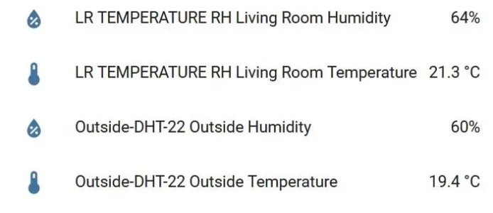
Now just tidy up the wires and print a new label. The middle LED says this pair of readings is shop Temperature and Relative Humidity.

I posted a 2 minute video to youtube showing the compressor running a fill cycle. You can see the temperature climb on the input to the radiator but comes out cool at the other end. Excuse the clang when I bumped into a pipe that fell.
Just need to tidy the wires and run it for a few weeks to see if anything else shows up.
Just need to tidy the wires and run it for a few weeks to see if anything else shows up.
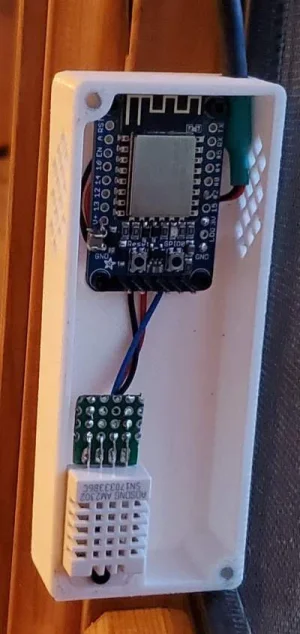
Working on Project #42 on the list. I have a couple of ESP8266 Wifi HUZZAH modules from Adafruit along with a few AM2302 RH + Temperature sensors. Like what I put inside the module attached to the compressor display. That one communicates via 1 wire protocol to the compressor monitor/controller.
WiFi versions will be added to my Home Automation system which I've dived back into after watching the HandsOnKatie videos. I went looking on the internet for a 3D printed box to hold these but the problem is that too many ESP8266 modules are different sizes and mounting configurations. So starting with the original as a guide of what I might make I created my own.

Still needs to be wired and then the HUZZAH programmed via the ESPHome link. Doing the CAD making the square vent holes was a learning experience.
For the photo I used a screw to hold the sensor in place. In reality the lid holds it in place. The screw isn't needed.

WiFi versions will be added to my Home Automation system which I've dived back into after watching the HandsOnKatie videos. I went looking on the internet for a 3D printed box to hold these but the problem is that too many ESP8266 modules are different sizes and mounting configurations. So starting with the original as a guide of what I might make I created my own.
Still needs to be wired and then the HUZZAH programmed via the ESPHome link. Doing the CAD making the square vent holes was a learning experience.
For the photo I used a screw to hold the sensor in place. In reality the lid holds it in place. The screw isn't needed.
I love modelling the stuff in CAD. Even then I find it takes a couple of prints to get there.

I love modelling the stuff in CAD. Even then I find it takes a couple of prints to get there.
I am truly jealous John. Sooooo cool!
Thank you. It's been a difficult road. Until I discovered Alibre I couldn't do CAD. Felt better and hurt less to bang my head against the wall. I could do PCB layouts and schematics although with the newer Altium compared to Protel that too has gone down hill. My mind works in mysterious ways and what works for most with respect to CAD does not work for me. Not sure why.I am truly jealous John. Sooooo cool!
For this RH and Temperature even the sensor and PC board was modelled. It's rough but it served the purpose to ensure that at least it would sort of fit. After that taking into account plastic shrinkage etc. was the next hard part.
A long way from attaching a heated head assembly in place of the Bosch Palm Router on my CNC system exactly 10 years ago.
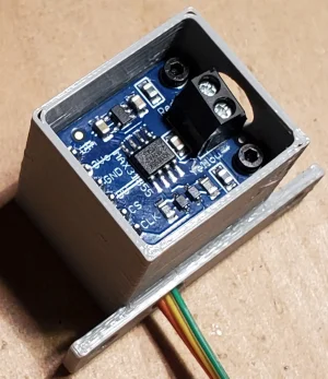
Something I should have done before I went to all the effort to create that little enclosure. Aiming my IR Temperature sensor at the little ESP8266 module I discovered that one corner of the module sits at 29C. And although I have the vent holes on either side and oriented it to have air flow through it appears that some of that heat still ends up impacting the DHT22 RH/Temp sensor.
Only by taking the lid off and dangling the sensor away from the box do I get accurate temperatures. I had read that the RF signal transmitting the temperature information was actually the cause of the heating of the sensor. And that may also be true of course but while the sensor is close enough to be heated from the bottom radiated heat from the ESP8266 it's a moot point whether RF is also to blame.
Time to design a different enclosure.
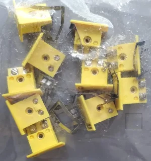
Got to run some errands. Will get back to the actual box later but at least now I can model the connector. Close enough given I'm using inexpensive calipers to measure it.

Now we would like some animation !!Got to run some errands. Will get back to the actual box later but at least now I can model the connector. Close enough given I'm using inexpensive calipers to measure it.
View attachment 50846
LOL
I remember in the early 90’s, we used ACAD version 5 to calculate material requirements for extruded and blow moulded HDPE corrugated pipe fittings. Big O Inc used to sell 75,000 Four inch ‘Tee’ connectors every year. The material was 40% of the inputs.
Definitely LOL...Now we would like some animation !!
LOL
I made the box a bit deeper and removed the mounting screw extrusion so there would be room to push in the mounting clip. Although unless I put screw driver holes in the side to access the mounting screws it's a one way trip with the metal hold down clip.