-
Scam Alert. Members are reminded to NOT send money to buy anything. Don't buy things remote and have it shipped - go get it yourself, pay in person, and take your equipment with you. Scammers have burned people on this forum. Urgency, secrecy, excuses, selling for friend, newish members, FUD, are RED FLAGS. A video conference call is not adequate assurance. Face to face interactions are required. Please report suspicions to the forum admins. Stay Safe - anyone can get scammed.
-
Several Regions have held meetups already, but others are being planned or are evaluating the interest. The Calgary Area Meetup is set for Saturday July 12th at 10am. The signup thread is here! Arbutus has also explored interest in a Fraser Valley meetup but it seems members either missed his thread or had other plans. Let him know if you are interested in a meetup later in the year by posting here! Slowpoke is trying to pull together an Ottawa area meetup later this summer. No date has been selected yet, so let him know if you are interested here! We are not aware of any other meetups being planned this year. If you are interested in doing something in your area, let everyone know and make it happen! Meetups are a great way to make new machining friends and get hands on help in your area. Don’t be shy, sign up and come, or plan your own meetup!
You are using an out of date browser. It may not display this or other websites correctly.
You should upgrade or use an alternative browser.
You should upgrade or use an alternative browser.
JCDammeyer's 42 projects
- Thread starter jcdammeyer
- Start date
Both Protel 99SE and Altium. But for commercial stuff I'm pretty well stuck with the "Enhanced User Experience" Altium which was the upgraded Protel. I stopped at Version 18 because the cost of maintenance was higher than what I was earning from using the package.
I still find Protel 99SE easier to use but Altium has a lot of features that make it much better. The down side, like all complex solutions, is one has to really use it all the time and pretty well only it as a full time job. I forget so much between uses that the more complex software is more difficult rather than easier to use.
For example Altium can make 3D images. Especially if you have 3D renderings of all the parts in the BOM and those are getting easier and easier to find or even draw them up from CAD and save as a step file.

This is handy because it can be exported as a STEP file which can then be placed inside a box that is also in CAD. I'll see if I can find an example. Meanwhile here's the end product from this set of drawings.

The little piggy back board is a PWM to 0-10V module that I used for the spindle before I changed to Step/Dir.
Each module takes the Step/Dir/Enable signals from the Break out Board (BoB) and translates them into the correct pinout for the AC Servo Bergerda DB25 pin connector. The Servo FAULT signal is on a different connector back to a common board that combines all the FAULT signals into one for the BoB.

I still find Protel 99SE easier to use but Altium has a lot of features that make it much better. The down side, like all complex solutions, is one has to really use it all the time and pretty well only it as a full time job. I forget so much between uses that the more complex software is more difficult rather than easier to use.
For example Altium can make 3D images. Especially if you have 3D renderings of all the parts in the BOM and those are getting easier and easier to find or even draw them up from CAD and save as a step file.
This is handy because it can be exported as a STEP file which can then be placed inside a box that is also in CAD. I'll see if I can find an example. Meanwhile here's the end product from this set of drawings.
The little piggy back board is a PWM to 0-10V module that I used for the spindle before I changed to Step/Dir.
Each module takes the Step/Dir/Enable signals from the Break out Board (BoB) and translates them into the correct pinout for the AC Servo Bergerda DB25 pin connector. The Servo FAULT signal is on a different connector back to a common board that combines all the FAULT signals into one for the BoB.
Attachments
Here's an example of a project. The box was designed by my client using their CAD software and exported as a step file. I designed the little heatsink that was machined by by the late Rick Salaga at Custom Machining. Altium was used for the PC board and Alibre was used to model the whole thing. Just to make sure everything fit before we had the boxes made in Salmon Arm BC.

Valid Manufacturing screwed up on the first box by not following the drawing dimensions so the lid didn't fit.

Now they all come out perfect.
Valid Manufacturing screwed up on the first box by not following the drawing dimensions so the lid didn't fit.
Now they all come out perfect.
Last edited:
Or an alternative of course is to just buy all the metal parts for $599US. This is what I have to build. Kind of intimidating when I look at how much needs to be made. Baby steps I guess.Thompson and NSK did have some ‘nice’ preload able ball screws with screw brushes to prevent chips from getting in the balls.
140mower
Don
....yup, just like eating an elephant, one bite at a time.Or an alternative of course is to just buy all the metal parts for $599US. This is what I have to build. Kind of intimidating when I look at how much needs to be made. Baby steps I guess.
View attachment 51518
slow-poke
Ultra Member
John,
I use Altium as well, I was an early adopter, 1988 when it was still called Tango (pre- Protel). When they released the 3D capability must have been about 20 years back, I thought sounds gimmicky, but after cramming 5lbs of electronics in a 2lb box several times, I quickly saw the light and have been fully 3D for a long time.
It's not perfect but it does a lot of things very very well when you dig deep into the menus. I hear you on you need to keep using it or you forget the short cut keys that are so handy. It took forever for so many of the pad's people to see the light. I recall reading a comparison between Altium and Pads and the comment was something like " using Pads is like drafting by pissing in the snow". That about sums up my experience with Pads. I found OrCad or whatever they call it now pretty decent. Fortunately Step files are really easy to find nowadays.
Used Tango. Also something called SCHEMA CAD (I either threw out the parallel port dongle or can't find it). I have drawings done in it that I can't migrate up.
Here's the header from one project.
;Tango-PCB PLUS V2.02 Series II
VERSION 1 3
FILE_GRA "E:\CAD\TANGO\ATI800.DRV"
FILE_PCB "C:\PROJECTS\DAM\PRODUCTS\DAM0012\PCB\DAM0012.PCB"
The PCB import into Protel.

The schematics not. Likely a library is missing that is somewhere other than the project folder.

Here's the header from one project.
;Tango-PCB PLUS V2.02 Series II
VERSION 1 3
FILE_GRA "E:\CAD\TANGO\ATI800.DRV"
FILE_PCB "C:\PROJECTS\DAM\PRODUCTS\DAM0012\PCB\DAM0012.PCB"
The PCB import into Protel.
The schematics not. Likely a library is missing that is somewhere other than the project folder.
Last edited:
John, I was just suggesting where you could buy the Ball Screw components, but . . . your time is your own, so go for it !! If you have all the tooling in your workshop.Or an alternative of course is to just buy all the metal parts for $599US. This is what I have to build. Kind of intimidating when I look at how much needs to be made. Baby steps I guess.
View attachment 51518
I am still working on my ‘Linear Slides’, when I can get my hands on affordable material inputs.
Hey Len,John, I was just suggesting where you could buy the Ball Screw components, but . . . your time is your own, so go for it !! If you have all the tooling in your workshop.
I am still working on my ‘Linear Slides’, when I can get my hands on affordable material inputs.
Thanks for the suggestions.
I had the set for my mill in my Misumi shopping basket at one point.
I've done all the CAD drawings to see what can fit and where for the ball screws. But then I got distracted with other projects like the power draw bar. Then the Knee upgrade from Stepper to AC Servo and I haven't properly finished that one mounting plate or the pulley covers.
There's no end to projects. <sad face>
Prioritize your efforts.Hey Len,
Thanks for the suggestions.
I had the set for my mill in my Misumi shopping basket at one point.
I've done all the CAD drawings to see what can fit and where for the ball screws. But then I got distracted with other projects like the power draw bar. Then the Knee upgrade from Stepper to AC Servo and I haven't properly finished that one mounting plate or the pulley covers.
There's no end to projects. <sad face>
Your projects inspire me to try more !!
Sideways off the projects list onto the must fix this now list and this is project #42 on that list... sigh...
Background. Still have to Photograph my son's larger things so I thought I'd set up with two slaved flashes and my Nikon all on tripods.
Oops. No way to mount the hot shoe of the flash onto the tripods I bought ages ago for some LED photo flood lamps that can mount on there. But I don't want to go through tons of batteries so I thought I'd use the flash units instead with the remote trigger head on the camera.
How I love 3D printing. Found a foot and printed two.
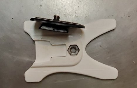
Pressed in the 1/4-20 nut and found the bottom was so thick that the tripod screw engaged about 1/2 to 3/4 turn. Don't want to drop $300 flash units if it's bumped and comes loose.
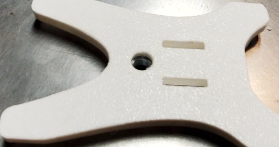
Each one takes about 01:15 to print and I'd have to try and convert an STL into STP so I could edit and reprint. Definite rabbit hole to go down. I could see the rest of the evening vanishing.
Instead I used my little Unimat DB-200 and turned two rusting old nuts down to have a shoulder that would extend through the plastic.
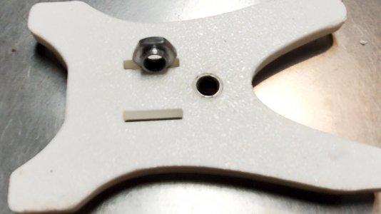
Now they are done. To get them that last little bit I threaded the nut onto a bolt and heated it with the propane torch. Then pressed it in and ran into the shop and used the 3T press to squish it down the last hare. (Yes I did mean to spell it that way rabbit holes and all).
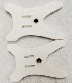
Now the tripod attachment thread has total engagement with the nut and my flashes are safe.
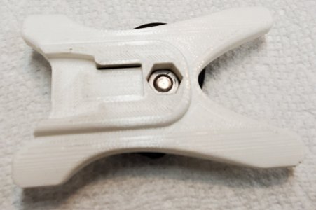
I really do like 3D printing. Yes an all metal solution could have been made but would also have taken some time. And as the flashes have lots of contacts on the bottom that part would have to be plastic anyway.
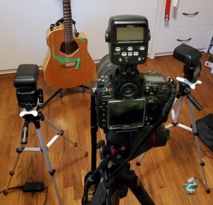
Background. Still have to Photograph my son's larger things so I thought I'd set up with two slaved flashes and my Nikon all on tripods.
Oops. No way to mount the hot shoe of the flash onto the tripods I bought ages ago for some LED photo flood lamps that can mount on there. But I don't want to go through tons of batteries so I thought I'd use the flash units instead with the remote trigger head on the camera.
How I love 3D printing. Found a foot and printed two.

Pressed in the 1/4-20 nut and found the bottom was so thick that the tripod screw engaged about 1/2 to 3/4 turn. Don't want to drop $300 flash units if it's bumped and comes loose.

Each one takes about 01:15 to print and I'd have to try and convert an STL into STP so I could edit and reprint. Definite rabbit hole to go down. I could see the rest of the evening vanishing.
Instead I used my little Unimat DB-200 and turned two rusting old nuts down to have a shoulder that would extend through the plastic.

Now they are done. To get them that last little bit I threaded the nut onto a bolt and heated it with the propane torch. Then pressed it in and ran into the shop and used the 3T press to squish it down the last hare. (Yes I did mean to spell it that way rabbit holes and all).

Now the tripod attachment thread has total engagement with the nut and my flashes are safe.

I really do like 3D printing. Yes an all metal solution could have been made but would also have taken some time. And as the flashes have lots of contacts on the bottom that part would have to be plastic anyway.

Last edited:
Here's the X axis lead screw on the mill. Pretty ugly and explains the backlash.John, I was just suggesting where you could buy the Ball Screw components, but . . . your time is your own, so go for it !! If you have all the tooling in your workshop.
I am still working on my ‘Linear Slides’, when I can get my hands on affordable material inputs.
This is one approach that I'm considering.
This was a different approach with a smaller diameter leadscrew.
But maybe to start with if I can internally thread the ACME pitch then just this to reduce the backlash.
Been lots of thinking about this. Very little progress. However I have modelled just about everything.
Last edited:
FYI - Even brand new lead screws have some backlash.
You have to learn to compensate for it.
Don’t try to TOTALLY eliminate the backlash, a leadscrew without some play (backlash) will bind and gall the threads.
The Ballscrew & Ballnut will also have a small amount of backlash.
The solution is to make sure you adjust for it during operation's.
You have to learn to compensate for it.
Don’t try to TOTALLY eliminate the backlash, a leadscrew without some play (backlash) will bind and gall the threads.
The Ballscrew & Ballnut will also have a small amount of backlash.
The solution is to make sure you adjust for it during operation's.
I've looked at the double stacked versions too. Not sure if they are worth it. Thing is right now a lot of backlashFYI - Even brand new lead screws have some backlash.
You have to learn to compensate for it.
Don’t try to TOTALLY eliminate the backlash, a leadscrew without some play (backlash) will bind and gall the threads.
The Ballscrew & Ballnut will also have a small amount of backlash.
The solution is to make sure you adjust for it during operation's.
From config file on X axis
# tested backlash at 4.2" from home 14MAR2020
#BACKLASH = 0.0205
Currently set at 0.014" but I really need to profile it over a larger area. With heavy climb milling into steel I've seen it pull the table. Not good. But then that photo of the ACME nut really tells all I think.
slow-poke
Ultra Member
I recently replaced the leadscrews with ballscrews on my 8x30 knee, was a bit easier than I expected.
A few FYI that might be useful:
- Mocking up with 3D models sped up the process.
- IIRC the Y nut (and for sure the leadscrews) can be removed with the X-table still on and at one extreme (although the extended table should be supported)
- The cheap ballscrews I used (eBay e-convenience) did have some backlash just less than the original leadscrew, I tweaked them for less. I also had some slop in the bearings and reduced that to near zero with matched angular contact bearings, the super cheap non matched angular contact bearings on Amazon etc are complete junk, don't waste the few dollars they sell them for.
- When adding the ballscrews to your one-shot oil distribution, be aware more than necessary oil will flow through the ballscrews, so you might want to add a restrictor(s)
- Looks like you have modeled most of what you need, but if you want any of my step models just ask and I will send them your way.
It is nice to have a machine that goes exactly where it is told to go. +/-0.0004"
OMG. +/-0.0004 in my dreams...I recently replaced the leadscrews with ballscrews on my 8x30 knee, was a bit easier than I expected.
A few FYI that might be useful:
- Mocking up with 3D models sped up the process.
- IIRC the Y nut (and for sure the leadscrews) can be removed with the X-table still on and at one extreme (although the extended table should be supported)
- The cheap ballscrews I used (eBay e-convenience) did have some backlash just less than the original leadscrew, I tweaked them for less. I also had some slop in the bearings and reduced that to near zero with matched angular contact bearings, the super cheap non matched angular contact bearings on Amazon etc are complete junk, don't waste the few dollars they sell them for.
- When adding the ballscrews to your one-shot oil distribution, be aware more than necessary oil will flow through the ballscrews, so you might want to add a restrictor(s)
- Looks like you have modeled most of what you need, but if you want any of my step models just ask and I will send them your way.
It is nice to have a machine that goes exactly where it is told to go. +/-0.0004"
View attachment 51570
That is a pretty high degree of accuracyOMG. +/-0.0004 in my dreams...
When we were inspection ground and lapped parts at Ex-Cell-O we would have stacked gauge blocks with a dial indicator on a marble table to verify those dimensions.
Maybe @slow-poke can provide some examples of his work.
slow-poke
Ultra Member
I won't pretend to have any expertise in this area. My comment is based on the value displayed on the linear scales.That is a pretty high degree of accuracy
When we were inspection ground and lapped parts at Ex-Cell-O we would have stacked gauge blocks with a dial indicator on a marble table to verify those dimensions.
Maybe @slow-poke can provide some examples of his work.
This system uses two feedback loops:
1) The inner is the encoder on the servo. It's close but does nothing to compensate for errors in the ballscrew, backlash, bearing slop etc. those errors seems to be in the 0.002-0.004" range depending on temperature etc.
2) The outer loop is based on the feedback from the linear scales.
LinuxCNC has a parameter for how close is close enough, if you set this to zero the servo just hunts back and forth at the destination trying to get to zero, so I have this parameter set to 0.00039"
Typical destination (according to the scales) is within that range. Scale accuracy is specified as +/-0.00026" per foot
Good enough for a hack hobby guy like me.
What have I missed?
Well a different approach I think to the tapered pattern is to do a bit more at the front end. I'm trying to create this part which is 3.5" diameter and the small bore is 2.5". Two tapered roller bearings fit in either end.Or an alternative of course is to just buy all the metal parts for $599US. This is what I have to build. Kind of intimidating when I look at how much needs to be made. Baby steps I guess.
View attachment 51518
So here's my drawing.
Core box to create the sand core. Two pieces are needed at just under 3 hours per piece.
The core will look like this:
And the pattern of which two are needed (3hr print time each)
Less after casting machining than making a tapered tube and cutting away a lot of metal. The cored pattern will result in removing about 1mm on the inside surfaces and on the outside.
I think the split pattern might be easier to just carve on the wood lathe. Core box too likely less time to drill a 72mm hole in each end and then a 60mm hole through the middle. Split it, add some filler putty and paint. The 3D printed materials will also require that filler and paint to make a decent pattern.
Lost foam or PLA is looking very attractive now.
