• Scam Alert. Members are reminded to NOT send money to buy anything. Don't buy things remote and have it shipped - go get it yourself, pay in person, and take your equipment with you. Scammers have burned people on this forum. Urgency, secrecy, excuses, selling for friend, newish members, FUD, are RED FLAGS. A video conference call is not adequate assurance. Face to face interactions are required. Please report suspicions to the forum admins. Stay Safe - anyone can get scammed.

Is Taper Attachment worth it?

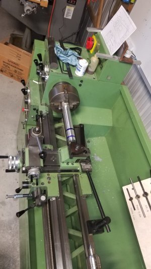
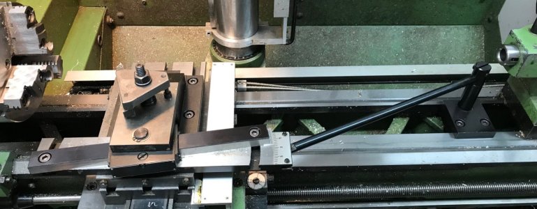
To achieve that, it looks like that slide is tethered to the lathe base with a rod so it is fixed in position on the Z axis independent of carriage motion. You can see the rod in one of @Darren ’s photos of parts in post #88.

Yes. I guess I assumed that all taper attachments did that. The OEM TA for my lathe does it like that too. So for me, that part was the easy part (the light bulb glow). I just couldn't see how that got translated into a solid tool movement to cut the taper.

I also wonder how much of cosine angle effect the tether bar has when doing large angle tapers.

Assuming that it's like the one for my lathe, it doesn't matter because neither the bar or the taper guide move once they are set and locked in place. Whatever sine error is there simply becomes part of the taper itself!

Whew! That’s complicated! The trade off here is the multiple slides (precision?)

If I have any remaining concerns, you have nailed it. There is lot going on there and my mind simply cannot grapple with their combined effects. By the time I have one nailed, I've forgotten how the one before it worked! I think they are simply additive. My biggest concern is flex in the taper guide dovetail-bar and the tether rod under load. I suspect small cuts are required to keep the cutting pressure load low - no big deal really.

Overall, I am VERY IMPRESSED!
 
you guys have the function pretty much nailed down. I'll have to get my ass in gear and get mine done and see how it works.

If i ever build another, I will use linear rails instead of dovetails for the 2 slides.

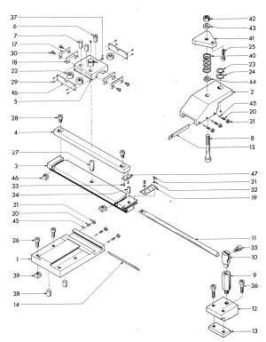
heres another pic (not my pic):
taper cutting attachment4.jpg
 
Last edited:
you guys have the function pretty much nailed down. I'll have to get my ass in gear and get mine done and see how it works.

If i ever build another, I will use linear rails instead of dovetails for the 2 slides.

heres another pic (not my pic):
That picture is worth a thousand word, it brings it all together!

I like how it's a nice modular way to add a generic TTA.

Edit: Works if you don’t have a threaded chuck mount….

D :cool:
 
Last edited:
Yes. I guess I assumed that all taper attachments did that. The OEM TA for my lathe does it like that too. So for me, that part was the easy part (the light bulb glow). I just couldn't see how that got translated into a solid tool movement to cut the taper.
Mine is the only one I've seen in person and it's different so it didn't click right away.

Assuming that it's like the one for my lathe, it doesn't matter because neither the bar or the taper guide move once they are set and locked in place. Whatever sine error is there simply becomes part of the taper itself

I'm nit picking for fun here but actually, the Z axis slide which the angle bar is mounted on will slide when the cross slide position is changed (with Z/carriage position unchanged) according to the cosine of the angle change in the tether rod created by X axis movement of the cross slide so a very small Z axis movement of the angle bar assy. will occur and trickle down eventually to reach the tool post. Said another way, if you had a DRO with both the cross and tool post axes combined then the reading would not be the same as the distance cranked in on the cross lead screw (if it were perfect).

Like I said, I'm nit picking for fun and that error will probably be swamped by play introduced by the various slides unless maybe you're doing a large angle taper and a long part.

D :cool:
 
I'm nit picking for fun here but actually, the Z axis slide which the angle bar is mounted on will slide when the cross slide position is changed (with Z/carriage position unchanged) according to the cosine of the angle change in the tether rod created by X axis movement of the cross slide so a very small Z axis movement of the angle bar assy. will occur and trickle down eventually to reach the tool post.

I think nit-picking is a good thing because it often leads to a better understanding. So as far as I'm concerned, nit-pick away! Others may not agree.

I think you are right in so far as the way you describe it. My understanding is again prejudiced by my experience where the angle bar holder does not move in or out with the cross-slide (it is attached to the saddle). But because the x position (front to back) of the angle bar holder on this design DOES change with the cross-slide position, I agree that there will be an effect - albeit very small - but only when the cross-slide is moved in or out with the handwheel. I think it can be minimized by doing the setup at the cross-slide position where the work will be done.

So here is the rub - buckle up for a rough ride..... The taper itself is not cut with a cross-slide adjustment. Only the intended depth of cut is set that way. So I think the effect you describe only affects the resultant depth of cut FOR THE ENTIRE LENGTH OF THE TAPER, it does not play a role in the taper itself. That means that even for the tiny amount that does happen, it will be dialed out as the overall taper OD is fine tuned - which must be done anyway. No?

Edit - might this be called nit picking the nit pick? LMAO!

Good catch! And fun too!
 
I'm nit picking for fun here but actually, the Z axis slide which the angle bar is mounted on will slide when the cross slide position is changed (with Z/carriage position unchanged)
I have an EMCO taper attachment for my SUPER 11 which is a similar design concept to the one on Darren's V13, although smaller. I changed mine from the EMCO designed assembly so that I could turn from the front. This increased the angle of the tether bar from what it would be if the TA was attached to turn tapers from the rear in reverse but it really is of no consequence.

TAPER ATTACHMENT.jpg

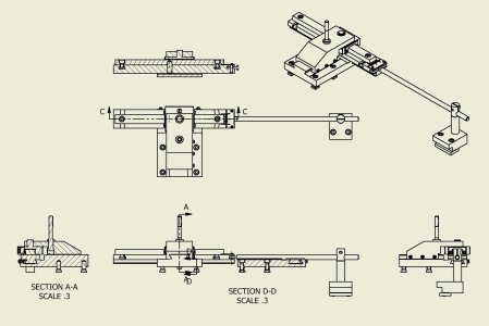
I was curious about the "nit-pick" so decided to lay out the geometry. Here's the layout for a 0.010 DOC.

TAPER JIG.jpg

The angle bar shifts along the Z-axis - in this case of a 0.010 DOC it shifts 0.00316. The DOC dialed in on the cross slide is reduced from 0.010" to 0.00949".
So I think the effect you describe only affects the resultant depth of cut FOR THE ENTIRE LENGTH OF THE TAPER, it does not play a role in the taper itself.

Correct - the resultant DOC does not play a significant role in the taper itself. I think that the resultant Z-axis shift is also not significant.
 
I have an EMCO taper attachment for my SUPER 11 which is a similar design concept to the one on Darren's V13, although smaller. I changed mine from the EMCO designed assembly so that I could turn from the front. This increased the angle of the tether bar from what it would be if the TA was attached to turn tapers from the rear in reverse but it really is of no consequence.

View attachment 39020
I was curious about the "nit-pick" so decided to lay out the geometry. Here's the layout for a 0.010 DOC.

View attachment 39019
The angle bar shifts along the Z-axis - in this case of a 0.010 DOC it shifts 0.00316. The DOC dialed in on the cross slide is reduced from 0.010" to 0.00949".


Correct - the resultant DOC does not play a significant role in the taper itself. I think that the resultant Z-axis shift is also not significant.

Agree with both of you that the depth of cut offset will be uniform through the Z travel.

Props to you for working out the math which I was too lazy to do! To state the obvious, in your case the variation is increased by the angle of the tie bar but if you’re only doing a minimal cumulative depth of cut then it isn’t significant.

If you have to do several passes to get a greater taper angle then it could be. </nitpic> ;)

D :cool:
 
Well, I believe I have Darren's/Emco's tapering unit figured out. It took a bit. Read it all over about 5 times, slept a few times, looked at Darren's pictures, then seen eotrfish's picture,that helped, realized Darren had 2 different PDF's, tossed out the South Bend set up I am familiar with, and enough dirt came off the old rock to see some light.
The unit itself has " 2"dove tails' "and then a "slide" on the sine bar! This makes it very much independent, while the cross slide can set the depth of cut.
 
Well, I believe I have Darren's/Emco's tapering unit figured out.

It's a complicated beast isn't it! Doesn't help much that all the slides and dovetails are not so obvious or that this animal is a bit different to anything else I've ever seen or used but yet quite misleadingly similar!
 
That is very true, once I found out the cutting head/holder block was moveing on a dove tail, it started to make me wonder. Then the sine bar being mounted on a bar with a dove tail, what the devil ! Eotrfish's picture with the link bar in it made me realize the link was able to pivit.
In no way like the South Bend unit! There were (no?)pictures showing those 2 dove tails.
But got it now!
 
NP! It was fun!

Now that you fully understand it, you can probably also see how simple it really is, and how adaptable this design could be to many different lathes. The unfinished unit that i built didnt take much to build. Like I said before, if i were to do it again, i'd probably make a sub plate and mount cheap linear rails to it for the slides. Super simple really.
 
It was good for the brain, didn't help the sleeping, but got used to that when doing contracting, figured out a lot of things for work at 1 or 2 in the morning.
 
It was good for the brain, didn't help the sleeping, but got used to that when doing contracting, figured out a lot of things for work at 1 or 2 in the morning.

For me, realizing I could solve problems in my dreams was a very powerful enabler. I never did sleep very well, so working on things till late at night meant I sometimes dreamed about them too. At first I was miserable about it - who wants 24/7 problems? Then one day I realized that I quite often woke up with clarity and solutions. So I started to deliberately think about my problems before falling asleep. It worked! A sleeping mind isn't fettered by a million distractions nor by all the assumed realities that often cloud our ability to imagine things as they really are.
 
Now that you fully understand it, you can probably also see how simple it really is, and how adaptable this design could be to many different lathes. The unfinished unit that i built didnt take much to build. Like I said before, if i were to do it again, i'd probably make a sub plate and mount cheap linear rails to it for the slides. Super simple really.

I'll have to sleep on that..... LOL!

The intent of this thread was to help me decide if a taper attachment was worth buying.

You have changed the initial question. Now I'm also wondering if it's worth making....
 
My lathe a Harrison M300 came with a taper attachment. I have only used it twice so far. So to answer your question is it worth it. I looked up the price to buy a new one for my lathe. The replacement cost is $4,947.83 USD. That's the price before shipping, exchange, taxes etc. I suppose to me if I had to make the choice a used one at less than $1k might be worth it. If I had to buy a new one the price would pay for a lot of trips to my friends machine shop where I could use his bigger lathe.
 
Back
Top