• Scam Alert. Members are reminded to NOT send money to buy anything. Don't buy things remote and have it shipped - go get it yourself, pay in person, and take your equipment with you. Scammers have burned people on this forum. Urgency, secrecy, excuses, selling for friend, newish members, FUD, are RED FLAGS. A video conference call is not adequate assurance. Face to face interactions are required. Please report suspicions to the forum admins. Stay Safe - anyone can get scammed.

Is Taper Attachment worth it?

"The cutting force when turning is a resultant force that combines tangential, feed and radial force components. These force components can be measured with a three-component force dynamometer. Metalcutting professionals consider Kistler dynamometers the most accurate.

Of the three cutting force components, the tangential force (FZ) is the greatest, the feed force (FY) is less in magnitude and the radial force (FX) is the least in magnitude. As a rule of thumb, the following relationships are used, but it is not a good practice because the results are not as accurate as they could be: FY = 0.50FZ and FX = 0.25FZ."


View attachment 38942
Thanks for the reference. This is good stuff.

An observation: Fr (or FY in the description) heavily depends on the nose geometry of the insert / cutting tool. I had it go negative (ie, the tool was “sucked“ into the part) and thus screwed up the dimension. (The lathe had a fair bit of backlash in the cross slide - hence the tool was able to pull in by the lash amount). This only happened at certain DoC, feed rate and insert used.

A great way to observe the Fr (FY) force (and rigidity issues) is after the cut is complete and the carriage is wound back to the start without retracting the tool. If the tool leaves a “witness spiral” you have had a lot of Fr (FY) tool pressure. If there is no spiral, then the tool was able to withstand the Fr (FY) force with its rigidity. If there is no spiral but you can see light between the tool and the work piece, Fr (FY) was negative and the tool was “sucked“ into the part.

Getting back to a TTA: since it introduces more moving components (each with a certain amount of clearance to make it work), one needs to be aware of backlash (and reduced rigidity) when using one. I found that was the biggest contributor to inaccurate angles. The sine bar set-up can be perfect, but it may still not give you the correct angle. So expect some trial and error.
 
@RobinHood @Susquatch

1. What am I missing here that you guys think that a sine bar would be inaccurate to setting your taper?

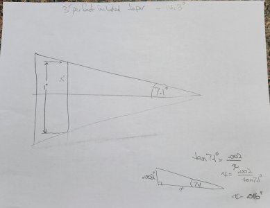
2. The balancing arbour has a dimension of 1" at the large end of the taper. Let's say while you're turning the taper portion of your arbour and you miss your mark by 0.004". If you have removed too much, the wheel adapter will seat 0.016" further along on that axis; if you are too thick, you are 0.016" further back. So what?
 

Attachments

  • 20231013_081227.jpg
    20231013_081227.jpg
    157 KB · Views: 3
  • Screenshot_20231013_081633_Chrome.jpg
    Screenshot_20231013_081633_Chrome.jpg
    68.6 KB · Views: 3
1. What am I missing here that you guys think that a sine bar would be inaccurate to setting your taper?
It is not the sine bar / set-up itself; it’s the extra bits and pieces of the TTA that have given “problems“ under the cutting forces in the past. Some are better than others, but all had some extra “slop” introduced in the compound mechanism.

I‘ve used them on Standard Modern (Made in Canada) lathes (2 of them), now I have them on the Colchester Master (Made in the UK) and the CMT Ursus (Made in Italy).

What I am trying to say is that it won’t be a set and forget operation - some fine tuning will be required after initial set-up with the sine bar.
 
2. The balancing arbour has a dimension of 1" at the large end of the taper. Let's say while you're turning the taper portion of your arbour and you miss your mark by 0.004". If you have removed too much, the wheel adapter will seat 0.016" further along on that axis; if you are too thick, you are 0.016" further back. So what?
I agree 100% that in that case it won’t matter one bit. It’s getting the taper angle right that is the challenge…
 
It attaches on the cross slide t slots and is therefore independent of the cross slide leadscrew.

I slept on it and didn't get any closer to understanding. This morning I saw your post and the light bulb is starting to glow. Your notes talked about cutting in reverse. Then I noticed this:

Taper Attachment In Use~2.jpg


BSo now I'm wondering how that slides or moves in relation to the cross-slide. Do the T-Bolts slide? Or does some part of the tool holder slide or rotate?

But I'm still missing something. How is the cutting tool linked to the taper guide? Does the whole holder slide in the T-Slots? Or does the tool itself slide in and out of the rear tool post with the taper guide?

I'm sorry to be asking so many basic questions. I guess I'm just feeling a bit dense right now.

The light bulb is glowing, but the room is still pretty dark.

Hopefully your next reply will close the circuit.
 
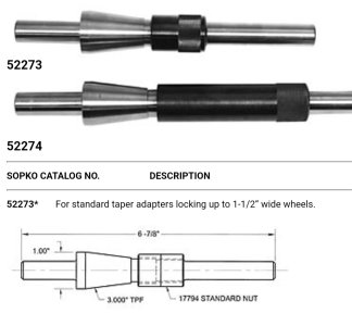
But you have a K.O. Lee surface grinder. Very reputable American company. If they specify a 3ipf taper for their spindle, you can be pretty sure that it is, unless it's scratched up or damaged. I would be more inclined to measure your adapter which is made off-shore.

That's my plan. Maybe even later today. My wife's sister and her hubby just left, and it's raining so no harvest for a few days. I tried a rough measurement with an angle Gage. It wasn't very productive, so I'll have to do it right this next time.

Remember what you are making, a balancing arbour. Its just a device to hold your wheel vertically. It doesn't warrant half a tenth cuts.

Yes, that's been the way I've been looking at it all along. I think all this fuss about perfection is just a lot of hooky for the most part. But since I have not actually done it yet, my instincts are as suspect as a sleeping snake..... So I'm trying to approach it in a way that it can turn out ok regardless. It's about balance not fit. So even a poor finish shouldn't matter as long as it's uniformly poor.

Wait til you start balancing and positioning those set screws on the balancing ring. It'll drive you mad!

Ya, I've been worried about that...... I had thought of doing some math first, but it might be better to go mad first and then do the math! LMAO!
 
Nothing slides in the t slots, its firmly anchored.

Right under the toolbit is a dovetail slide running in the same axis as the cross slide. That is linked to the angle bar. The angle bar and its slide are anchored to the lathe bed. As the carriage moves, the angle bar remains stationary. This causes movement of the toolbit as it is linked to, and follows the angle bar.

it works the same as any other TA, with the difference being that instead of being linked to the cross slide, it has its own cross slide and tool holder. So, in my mind, it would be simpler to adapt to a lathe because you don't have to mess with the lathe at all. Its a complete separate attachment.
 
I agree 100% that in that case it won’t matter one bit. It’s getting the taper angle right that is the challenge…

I'm hopeful that the hollow section in the adapters - basically two tapers, one at the fat end and one at the thin end will be my friend. Some prussian blue and some fine tuning should get it right for balancing purposes even if the taper isn't all that good - ie because it's a static balance with no loads, all I really need is two concentric rings of contact. But maybe I'll get two feet of bar just in case..... LOL!
 
Nothing slides in the t slots, its firmly anchored.

THANK YOU DARREN! The light bulb is on full output. That's what I was missing! Basically A slides on B on the same axis as the cross-slide according to the taper bar!

Taper Attachment In Use~3.jpg


I really appreciate your patience with me Darren. I can be quite thick sometimes. But I'm never really happy till I actually understand and I don't like to say "I get it" until I really do.

Nice!

It's a lot of parts moving but it's also quite elegant. I wouldn't need the T-Slots. Four threaded holes and some machine screws would work just fine.
 
A HSS shear tool will be your friend. Even sharp carbide works just fine (I use inserts made specifically for ALU or SS) in tool steel regularly to take sub-thou DoC. The other option is a sanding stick to remove the last tenth or so.

I'm a big fan of shear tools, and even have one I have thought about patenting but the revenue stream would never pay for the legal costs.

I confess that I have not had foolproof success with a shear tool on harder steels. In any event, this business about steel type and hardness is just a red herring. I really just wanted to know what steel @thestelster used to make his arbour.

Normally I would use what ever I have laying around, but in this case that would be big old machinery bolts and shafts and I didnt think they would be up to the job. So it's hard to beat whatever worked for someone else.

It can all be managed when I actually start making chips. For one thing, as mentioned on another post, I don't think finish really matters for this job anyway.
 
Last edited:
But you have a K.O. Lee surface grinder. Very reputable American company. If they specify a 3ipf taper for their spindle, you can be pretty sure that it is, unless it's scratched up or damaged. I would be more inclined to measure your adapter which is made off-shore.

So I setup on the surface grinder table and measured the spindle taper as best I could.

You were absolutely right. It's as close as I could measure to 7.24 degrees - which is half of 3 over 12. So I have my target taper. I ordered a 1" 4140 bar. I was gunna go 1.5, but couldn't see why that waste was required. I'll center it and clean it up so it's concentric, but I'm not gunna fuss if that makes it 15/16ths. The inside of the fattest of the two tapers is 0.89 and the outside is roughly 0.96 so I have a tenth to play with and still hit the fatter taper for balancing.

Depending on the weather, I'll prolly pick it up on Monday.

Need to make at least one balancing ring in the meantime to play with and meet that monster you talked about.... LOL!
 
You could make a nice little pallet with a decent hole pattern and mount it in place of the compound. Not quite a t-slotted cross slide, but it would still allow setups for line boring etc.

This idea has simmered in my brain since you mentioned it. You are quite right. It's easy to do as such things go and it would address a good 3/4 of my wants. If I drilled and tapped the four holes I mentioned above, they could easily hold a plate like that.

One more very nice project on my list!
 
The few grinding wheel balances I have seen and used have looked like the old style tire balancers, the cone on top of the pointed spike. They worked well, more so then I thought they would. Then I was also balancing stones from 24? in. to 30 in.
I tried one the first time with great doubt, balanced grinding wheel as close to level as I could, turned 180 degrees, checked, was good, turned again 30 degrees or so, and checked again, was good. Spun up on the grinder, all was good. Trued face and sides, rechecked balance, needed very slight adjustment from trueing.
The only thing I would check, was that distance was even all around balancing hub to stone hub.
Not sure if this type of balancer could be used with much smaller stones.
Note- this was on crank grinder stones.
 
I still have not figured out how the depth of cut is adjusted on Darren's tapering device. I could not see the dove tail under the cutting block which also had me wondering. Now that part I get. DOC, ain't got that yet.
 
you use the lathes original cross feed for doc adjustments. It moves the whole TA because its bolted to the cross slide
 
I still have not figured out how the depth of cut is adjusted on Darren's tapering device. I could not see the dove tail under the cutting block which also had me wondering. Now that part I get. DOC, ain't got that yet.

You have lost me as well.... Maybe a video demonstration is in order.

Maybe I can help as a fellow who has finally seen the light after being in the dark..... LOL!

The regular cross slide hand wheel moves the whole cross-slide in or out. This includes the new rear block and cutting tool. So it sets the overall DOC. The only difference between this and a regular lathe is that the cutting tool is behind the work.

However the cutting tool itself can also move in and out as it follows the taper adjustment bar. So the two amounts (cross-slide amount and taper amount) get added together. The cross-slide amount is fixed at whatever you dial in, but the taper amount changes as it follows the taper guide which depends on how far or how close it is to the chuck. The overall result is a taper.

You can also think of it a bit like a compound that is turned 90 degrees so it follows the same axis as the cross slide. You can use both the cross-slide or the compound to adjust the DOC. But in this case, instead of a compound, the taper adjustment follows a taper guide that depends on how far it is from the chuck.
 
I still have not figured out how the depth of cut is adjusted on Darren's tapering device. I could not see the dove tail under the cutting block which also had me wondering. Now that part I get. DOC, ain't got that yet.

EDIT: I was having my say on it but @Susquatch types faster than me so I'll just expand on a couple of details. ;)

I’ve been eyeing this for a couple of days and then the light came on, here's my take. There’s one key detail that we don’t see in the photos in this thread but it can be seen in @Darren ’s other thread.

@Susquatch points out that the taper angle slide bar is mounted to the cross slide so the DOC can be controlled by the cross slide but the subtle detail is that the angle bar arrangement is mounted on a Z axis slide you don't see in the photos in this thread. It can be seen in some of the photos of @Darren 's other thread. That's important because the carriage has to move in the Z axis relative to the angle bar to drive the tool post slide on the X axis to give you a tapered cut. It won't if it's simply fixed to the cross slide.

To achieve that, it looks like that slide is tethered to the lathe base with a rod so it is fixed in position on the Z axis independent of carriage motion. You can see the rod in one of @Darren ’s photos of parts in post #88.

Finally, the tool post mount with it’s X axis slide is linked to the taper angle adjuster bar so that when the carriage moves (Z axis) relative to the angle bar, the tool post moves in the X direction following the angle of the adjuster bar.

Whew! That’s complicated! The trade off here is the multiple slides (precision?) vs. having to disengage the cross slide nut like my Myford or an SM. I also wonder how much of cosine angle effect the tether bar has when doing large angle tapers.

Speaking of my Myford, I put the TTA to use again today to cut a taper on a shop vac attachment. It’s made from pipe and too short a piece to put between centres to use the offset method but since I can measure the angle setting with the (Touch)DRO, doing the setup was a snap compared to fiddling with the compound. Surface finish was great too!

D :cool:
 
Back
Top