• Spring 2024 meetup in Calgary - date Saturday, April 20/2024. discussion Please RSVP Here to confirm and get your invitation and the location details. RSVP NOW so organizers can plan to get sufficient food etc. It's Tomorrow Saturday! you can still RSVP until I stop checking my phone tomorrow More info and agenda
  • We are having email/registration problems again. Diagnosis is underway. New users sorry if you are having trouble getting registered. We are exploring different options to get registered. Contact the forum via another member or on facebook if you're stuck. Update -> we think it is fixed. Let us know if not.
  • Spring meet up in Ontario, April 6/2024. NEW LOCATION See Post #31 Discussion AND THE NEW LOCATION

Hendey T&G Lathe

Rauce

Ultra Member
@Mcgyver gets to say he told me so now :rolleyes:

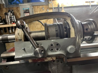
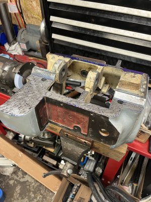
I did the blue check with the headstock just now. The bluing alone tells me I have good contact on the flat surface.

I also got out an indicator to check for rocking/soft foot since it’s 4 points essentially. I was able to measure 1-2 tenths of rock across two corners which I’m thinking is acceptable.

The other check I did was to see if it’s seated in the angled ways… and it isn’t. With the bolts just snugged down I can move the headstock about .003” from hitting the angled way on one side, to the other.

So I will have to scrape the flat down a bit to get full contact on the angled ways.

I’m thinking this is the better of the two ways it could go if it’s going to be out.

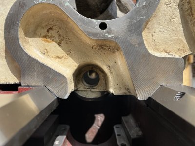
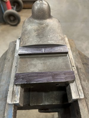
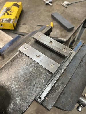
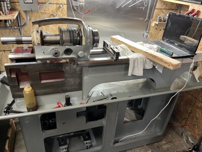
Edit: here’s a photo showing the surfaces the contact.
 

Attachments

  • 0A9EBB29-FEE4-435F-9F55-48A2E96000F7.jpeg
    0A9EBB29-FEE4-435F-9F55-48A2E96000F7.jpeg
    471.7 KB · Views: 16
Last edited:

Rauce

Ultra Member
Plan is taking shape. I cleaned off the surface plate and heaved the headstock up there on some 2-4-6 blocks. I’m going to take a bunch of height measurements wherever I can before I begin scraping so I know how much I’m taking off.

I’m going to sit down and do some trig in a bit to figure out how much it needs to drop based on my .003” measurement.
 

Attachments

  • F0E6F741-7385-4592-81BC-B5E0F4222A71.jpeg
    F0E6F741-7385-4592-81BC-B5E0F4222A71.jpeg
    639.2 KB · Views: 14

Rauce

Ultra Member
I’ve been scraping away and getting pretty close now.

After getting it to sit tight in the angled ways it was out a thou in both directions across 12”. I’ve done a few passes now to remove those errors and I’m at 2 tenths low and 7 tenths toward the front/apron side at the far end.

Ideally looking for 0-4 tenths towards the front and 0-4 tenths high at the end of the bar according to Testing Machine Tools by Schlesinger.
 

Attachments

  • C5CA9634-AAAF-46E2-9A56-F9FF45669FA6.jpeg
    C5CA9634-AAAF-46E2-9A56-F9FF45669FA6.jpeg
    547.4 KB · Views: 18
  • A1BD972E-DA9C-4751-BA5F-16D0C0B42D6B.jpeg
    A1BD972E-DA9C-4751-BA5F-16D0C0B42D6B.jpeg
    600.3 KB · Views: 17

Rauce

Ultra Member
Strangely it seems to move a tenth or two in the direction I’m trying to get it to go just sitting overnight in between sessions working on it. Measuring to tenths is tricky business.

I think it’s as good as it’s going to get. Somewhere in the middle the of the 0-4 I’m looking for.

In other areas of the project I got some work done on the coumpound repair.
 

Attachments

  • 34715BC6-09F6-4ED6-B080-C24B3D1FFFA7.jpeg
    34715BC6-09F6-4ED6-B080-C24B3D1FFFA7.jpeg
    558 KB · Views: 13
  • 1BD17133-FF25-4695-B115-5A92C802CC11.jpeg
    1BD17133-FF25-4695-B115-5A92C802CC11.jpeg
    682.8 KB · Views: 14

LenVW

Process Machinery Designer
Premium Member
Hey Ross, if you are looking for other innovative machine shops in Hamilton,
you can try these two:
- Kodarin Industries
- Wentworth Tool & Mould

I contracted both to do large mould jobs for me in the 1990s.
 

Rauce

Ultra Member
I got the lathe moved into my shop on Thursday night. Was about as difficult as I expected. Not terrible but it took about an hour. The doorway was a close fit.

I modified the existing motor mount adapter to work with the 143 frame clearpath servo.

I also ran the servo controlled by the clearpath setup software via usb. It’s not yet connected to the drive system since I’m waiting on a taperlock bushing for the smaller 7/8” shaft on the servo.

I also ordered a whole bunch of electrical stuff for the controls. Switches, E-stop, solid state relay, encoder, 12v power supply, din rails, terminal blocks for 12v DC distribution, circuit breaker (13a as recommended by the clearpath manual).

Tonight I pulled the 2x4s out from under it and tried to level it using the built in levelling screws and some rubber feet I got at PA. Seems like the rubber is way too soft. I was able to get it level-ish but it wobbles pretty easy if you push on it because of the rubber.

I think I’ll probably do some aluminum feet that the set screws in the base will fit into instead.
 

Attachments

  • AE6BBB65-E2D7-4579-B59F-523CAE4F050C.jpeg
    AE6BBB65-E2D7-4579-B59F-523CAE4F050C.jpeg
    340.6 KB · Views: 17
  • 3822FC61-6068-438B-A675-F294940B39FA.jpeg
    3822FC61-6068-438B-A675-F294940B39FA.jpeg
    579.1 KB · Views: 16

Mcgyver

Ultra Member
@Mcgyver gets to say he told me so now :rolleyes:

haha, none of that, just want to see you get that lathe back its former glory. I have some experience at it and have paid attention to the topic, reconditioning, for a long time. Just like any more complex machining task, there's logic to the process and sequence.

It would be really good for you check the tailstock before more on the HS. In all likelihood it will be out as well, and the usual approach is to scrape the tail stock first then the HS. Done as the TS is always going to lower (bottom of HS doesn't wear) and that sequence lets you get them aligned.

You also really need to scrape the saddle first since you are using it as a sled for the indicator. It will NOT be mating properly and will make a mess of things if not scraped in with proper bearing on the ways. You could use a machine tool alignment device, but the saddle has to be done at some point anyway.

Use the ground bed to spot all three. This lets you get the mating/contact you need for rigidity/full support. You also need to level the lathe before spotting to the bed (to ensure there is no twist). Use a 199 Starrett to level it, there is not much else comparable and this op needs to be precise. Without doing so, indicating a test bar is meaningless.

Its challenging, bringing the HS in means horizontal and vertical alignment with the the TS as well as to the bed in two planes, but that lathe is worth it!

With the test bar, are you measuring then rotating 180 and measuring again? That lets you eliminate any error in its mount....in fact doing it that way, you don't even need an "official" test bar, just something ground round and straight.
 
Last edited:

Rauce

Ultra Member
I did check the tailstock, its the same issue with the fit, the regrind did change the the geometry slightly.

Fortunately because the headstock was taken from another machine by Peter to make this one whole, it was actually a few thou lower than the tailstock to begin with. I figured I could do it this way around and tackle the tailstock after.

Thanks for the other tips. I’m going to get it level and scrape in the carriage and then do some rechecks to see if I need to go back and adjust the headstock again.

I was rotating the test bar to account for error in straightness. The test was pretty good so it made the calculations easier. Depending on how it was clocked in the spindle MT bore I had 4-7 tenths TIR at the end of the 12” bar. Diameters at the two ends of the test bar are as close as I can repeatably measure (+/- a tenth or better).

I think I’ve found an undamaged back gear from another hendey restorer with a parts machine so the headstock will be coming apart again when that arrives.
 

Susquatch

Ultra Member
Administrator
Moderator
Premium Member
I did check the tailstock, its the same issue with the fit, the regrind did change the the geometry slightly.

Fortunately because the headstock was taken from another machine by Peter to make this one whole, it was actually a few thou lower than the tailstock to begin with. I figured I could do it this way around and tackle the tailstock after.

Thanks for the other tips. I’m going to get it level and scrape in the carriage and then do some rechecks to see if I need to go back and adjust the headstock again.

I was rotating the test bar to account for error in straightness. The test was pretty good so it made the calculations easier. Depending on how it was clocked in the spindle MT bore I had 4-7 tenths TIR at the end of the 12” bar. Diameters at the two ends of the test bar are as close as I can repeatably measure (+/- a tenth or better).

I think I’ve found an undamaged back gear from another hendey restorer with a parts machine so the headstock will be coming apart again when that arrives.

I've never done what you are doing. So I can only imagine the challenges.

I am thoroughly enjoying reading about your adventures. On first blush, I do agree with @Mcgyver . I don't know how you can fix either end until the carriage runs true. Otherwise you are always chasing your own tail. In my opinion, you have to assume the bed regrind was perfect and focus on the best possible levelling you can get without a working lathe. To me, that means accepting the chicken and egg paradigm and iterating to get there.

I admire your determination and your courage. I'm sure that you and Mcgyver are both an inspiration to most of us too.
 

Rauce

Ultra Member
I think I made a couple of assumptions that maybe I shouldn’t have?

1. That as long as the carriage was solid on the ways (not rocking or twisting) it wouldn’t matter if it was scraped in to full contact yet as it would still follow the ways as straight as the ways are for the purpose of inspecting headstock alignment.

2. That this lathe being relatively small and very stout (cast iron base cabinet and bed are ~1000lbs each and the entire lathe once assembled is around 3000lbs) would be be almost completely resistant to twist.

I think you guys are right and I’m best served to re-examine my assumptions here. Maybe I’m right about one or the other but it’s better to find out now if I’m wrong than to be left scratching my head later.
 

Mcgyver

Ultra Member
I think you've come to the right conclusion, just to pile on to make sure you don't waiver :D......those assumptions make intuitive sense.....but a tenth is awfully bloody small! To have a fighting chance you're better eliminating possible sources of error.

The 10ee's for example have the bottom of the base resting on three points. They are equally massive, but rest on three points as the maker thought their weight could introduce twist.

A lot of guys feel those beds should be ground while on the base which makes some sense with three points of contact to the floor. If the bed is taken off the base it can create some twist if the the top of the base is not as flat as the grinder. If your base rests on three points, you'll have to level by shimming between the base and bed. If it doesn't rest on the three points, level in the usual fashion

Either way, you are striving for the highest levels of accuracy, so remove in sequence that which can bite you.

On the saddle, it has to be scraped anyway, right? Its needs to mate properly for operation to make rigid and to minimize wear. Since it has to be, if you do it now you remove the chance of there being any rocking. You might not feel a few tenths rocking, but it could mess up your measurement.
 

Susquatch

Ultra Member
Administrator
Moderator
Premium Member
I think I made a couple of assumptions that maybe I shouldn’t have?

1. That as long as the carriage was solid on the ways (not rocking or twisting) it wouldn’t matter if it was scraped in to full contact yet as it would still follow the ways as straight as the ways are for the purpose of inspecting headstock alignment.

It was actually a good assumption. However it's still an assumption. If the carriage can rock on the ways in any direction, even ever so slightly, either up or down, there goes that.

2. That this lathe being relatively small and very stout (cast iron base cabinet and bed are ~1000lbs each and the entire lathe once assembled is around 3000lbs) would be be almost completely resistant to twist.

Remember this if you remember anything I have ever said. Absolutely EVERYTHING no matter how big, how strong, how heavy, how thick, how solid - WILL DISTORT in reaction to a force. It is not IF, it is only HOW MUCH.

Fundamentally, something twice as stiff, distorts half as much. 10x as stiff - 1/10th as much. 100x as stiff - 1/100 as much. Etc etc

You can dramatically change the stiffness by making even small changes in geometry, but you cannot change the laws of physics - at least not in conventional space/time. The material properties and the geometry dictate how much a part deforms in response to a force. But it WILL deform - no ifs ands or buts.


I think you guys are right and I’m best served to re-examine my assumptions here. Maybe I’m right about one or the other but it’s better to find out now if I’m wrong than to be left scratching my head later.

ALWAYS the better and wiser path forward - unless the bean counters or SWMBO has you by the man parts...... In that case it's often best to jump first and scratch later....... LOL!
 

Rauce

Ultra Member
The bed rests on 4 levelling screws built in. They’re 7/8” or maybe 1” dog point set screws with locking nuts. Interestingly they are not all at the 4 corners of the base. The front tailstock side levelling screw is positioned about 6” back from the front of the base and the rear tailstock side is position about 6” in towards the middle of the base. The head stock screws are essentially at the corners. I’m guessing there’s some reason for this related to weight distrubution.

The bottom of the bed where it attaches to the base was scraped flat at the factory. When I had it ground they checked several times throughout the process that it was sitting solid on the mag chuck and not warping in anyway. It stayed flat and solid throughout the process.

The bed side of that connection between the base and the bed was milled with a big fly cutter at the factory.

I’ve heard the same thing about grinding it while it’s attached to the base. It wasn’t really possible at the place I ended up going to so I figured I’d take what I could get. We’ll see once I get a precision level on it if I got lucky.
 

Susquatch

Ultra Member
Administrator
Moderator
Premium Member
Consider doing a best and worst case analysis. Pretend the entire bed is a solid block of cast iron and calculate the deflection from its own weight. Then do the same with a standard cross section that nearest approximates the bed cross section. That will tell you what the reasonable numbers are. They won't be much. But they will tell you what you can chase - if you want to.

With only 4 screws, it is difficult to do more than remove twist - which is a major factor all on its own. Yes, there are ways to address bending too, but one step at a time. No point trying to deal with the unknown till its known.

In the end, you can get close but perfection is impossible. However, knowing what you have, allows you to compensate - and that in itself is a powerful approximation of perfection. Together with the math above, and subsequent testing, you can learn what you have and then take that into account with your future work.
 

Rauce

Ultra Member
I levelled the lathe during the week. After getting it the first time I had to make adjustments for another couple days until it settled.

Forgot to take pictures but I used my master level (VIS .0005/10” resolution) and 1-2-3 blocks on the flats and v blocks on the v ways. I measured very little twist if we want to call it that. It was 3 tenths variation between the two flat ways. The v ways were similar, maybe more like 2 tenths over the length of the bed. This is right around what the grinding shop claimed (a tenth per foot) I did try to see if the levelling screws had any effect on this but I could not get it to change.

Since that’s been done I’ve acquired a bunch of electrical stuff for the controls and made some small parts.

The old high/low selector was a pretty rough cast lever that had been braze repaired at some point so I made a new one. The detents in the head casting are worn out so I made a plate that will screw on behind the lever that will get new detents.

I also made a cover for where the spindle lock goes. Late model Hendey T&Gs didn’t have it so my spindle pulley doesn’t have the drilled holes for the locking pin. Since my machine had the damaged headstock casting replaced with one from an older model the opening is there.
 

Attachments

  • 1F7C58D3-0E76-433C-AA13-0AD18FB37A12.jpeg
    1F7C58D3-0E76-433C-AA13-0AD18FB37A12.jpeg
    481.9 KB · Views: 10

Susquatch

Ultra Member
Administrator
Moderator
Premium Member
This is right around what the grinding shop claimed (a tenth per foot) I did try to see if the levelling screws had any effect on this but I could not get it to change.

I found that the last little bit took several months to settle out on mine. But eventually it got to where I couldn't measure it anymore.
 

Rauce

Ultra Member
Yeah I’ll keep checking the ways with my level as I work through some other stuff.

The clearpath AC servo is giving me some trouble at the moment. When I ran it uncoupled with default tuning (which is for an uncoupled motor) it was amazingly smooth and steady at a given rpm and ramping between speeds. After coupling it to the drive system and running the auto tuning software it’s very unsteady. Rpm is constantly fluctuating and varies wildly when ramping between speeds.

I’ve emailed them and hopefully there’s an easy fix. Otherwise I’ll be back to the previous plan and I’ll use the 3hp 3p motor and VFD that came with it.
 
Top