Hendey T&G Lathe

Rauce

Ultra Member
Looks good Ross.
If you want to add ‘closed lub’ cannisters, SKF has a line of units that may work instead of the gears in an oil bath.
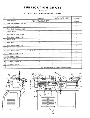
This machine is kind of unusual, there’s no oil baths at all. aside from the ways pretty much everything on the machine is grease lubricated. Seems to have worked since the gears, shafts and bushings are all in good condition but the grease really builds up over time. I was scooping out handfuls from that gear box.
 

a smile

Lifelong hobby - cold iron
Premium Member
I always thought that there would be uniformity issues with paste grease lubrication unless it was reapplied at a set time, so viscosity is a very important option
 

Rauce

Ultra Member
I’m using a no.2 Mobil grease. The important thing for grease selection on this machine is that greases with EP additives can corrode bronze so they shouldn’t be used. I looked at a lot of data sheets from grease manufacturers to find products that had results for a copper corrosion test of 1a or 1b.

I have read that some Hendey T&G owners use 600 weight steam cylinder oil instead
 

Attachments

  • IMG_0026.jpeg
    IMG_0026.jpeg
    383.6 KB · Views: 7

Rauce

Ultra Member
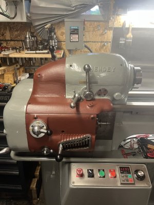
After some fiddling the guick change gear box is working as it should now. The pieces with red primer will come off again later to get the top coat.

I still have apron to dissemble and clean and the pieces that hold the lead screw and feed shaft. I also have to machine a new feed shaft. The original has some wear in the middle. I got some keyed shafting in the right size but the ends need to be machined to match the original.
 

Attachments

  • 0411F17B-45C5-4711-9986-BCB521EF4162.jpeg
    0411F17B-45C5-4711-9986-BCB521EF4162.jpeg
    478.8 KB · Views: 14

LenVW

Process Machinery Designer
Premium Member
After some fiddling the guick change gear box is working as it should now. The pieces with red primer will come off again later to get the top coat.

I still have apron to dissemble and clean and the pieces that hold the lead screw and feed shaft. I also have to machine a new feed shaft. The original has some wear in the middle. I got some keyed shafting in the right size but the ends need to be machined to match the original.
Nice work. Value added for sure.
Today I met a guy at the Cherry Park Festival in Kitchener. He had a restored 1934 Studebaker Commandor sedan on display. It was manufactured at the plant in Hamilton until 1954.
 

Attachments

  • 20230708_135743.jpeg
    20230708_135743.jpeg
    601.7 KB · Views: 5

Susquatch

Ultra Member
Administrator
Moderator
Premium Member
After some fiddling the guick change gear box is working as it should now. The pieces with red primer will come off again later to get the top coat.

I still have apron to dissemble and clean and the pieces that hold the lead screw and feed shaft. I also have to machine a new feed shaft. The original has some wear in the middle. I got some keyed shafting in the right size but the ends need to be machined to match the original.

I love it! It is looking BEAUTIFUL You are doing awesome work that you can be very proud of!
 

Rauce

Ultra Member
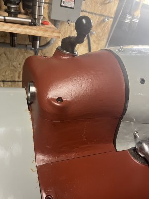
Forgot to mention… I need to decide what to do about this mismatch.

The original cracked headstock was replaced by the previous owner with one from an older Hendey and the castings must have changed slightly during production.

I can leave it or try and do some “bodywork” I was thinking about building it up a bit with the metal filled bondo and then skimming the top with regular bondo (which sands easier). What do you all think?
 

Attachments

  • 4D22335A-08E2-49CC-B042-863A7B6FFE4B.jpeg
    4D22335A-08E2-49CC-B042-863A7B6FFE4B.jpeg
    345.8 KB · Views: 19

a smile

Lifelong hobby - cold iron
Premium Member
After some fiddling the guick change gear box is working as it should now. The pieces with red primer will come off again later to get the top coat.

I still have apron to dissemble and clean and the pieces that hold the lead screw and feed shaft. I also have to machine a new feed shaft. The original has some wear in the middle. I got some keyed shafting in the right size but the ends need to be machined to match the original.
This is a very nice fix, I like the line and all, I see you extended the drive panel control line and installed the panel to the console. I don't think this is the best option, because you probably won't set the parameters of the inverter frequently. Secondly, the use of terminal control will make the operation panel look cleaner, and it is best to increase a low speed frequency (about 2-3hz), which will help you successfully complete the mechanical gear switch in the peristaltic state, rather than using manual rotation of the spindle to help the gear mesh.
 

Rauce

Ultra Member
This is a very nice fix, I like the line and all, I see you extended the drive panel control line and installed the panel to the console. I don't think this is the best option, because you probably won't set the parameters of the inverter frequently. Secondly, the use of terminal control will make the operation panel look cleaner, and it is best to increase a low speed frequency (about 2-3hz), which will help you successfully complete the mechanical gear switch in the peristaltic state, rather than using manual rotation of the spindle to help the gear mesh.
I am using terminal control with the buttons and potentiometer on the panel. I wanted the VFD display and keypad present only to change parameters and perform a reset if needed. I plan to add a hard cover with a window over the keypad to keep it from being damaged.

Performing reset or changing parameters may be infrequent but it would be difficult to remove the console to access the VFD if I needed to.
 

Susquatch

Ultra Member
Administrator
Moderator
Premium Member
What do you all think?

I'd leave it. It looks fine. Castings often don't match well.

No body else will notice but you. But you will notice either way so why take the risk of having to deal with a body filler mismatch.

Just my rather useless opinion.
 

RobinHood

Ultra Member
Premium Member
What do you all think?
How about mocking up a “transition fillet” using playdo putty? Then leave it on for a bit and your mind will decide what looks better over time as you work on other parts.

If you don’t like the shape, just get rid of it and / or redo it until you come up with something you like.
 

a smile

Lifelong hobby - cold iron
Premium Member
Forgot to mention… I need to decide what to do about this mismatch.

The original cracked headstock was replaced by the previous owner with one from an older Hendey and the castings must have changed slightly during production.

I can leave it or try and do some “bodywork” I was thinking about building it up a bit with the metal filled bondo and then skimming the top with regular bondo (which sands easier). What do you all think?
The gray color parts are polished into curves and the iron red parts are smooth and smooth, and then the paint becomes gray and white, you will find that the visual Angle will be coordinated.
 

Rauce

Ultra Member
Scraping in the saddle ways has been a long process. I think I’ve been at it for at least 3 weeks.

I’m any case I think I’m done. It’s probably not the best scraping job out there but all four surfaces have contact along the whole length.

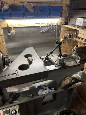
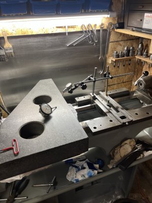
Today I popped the granite square up on the ways and aligned one edge with the carriage travel.

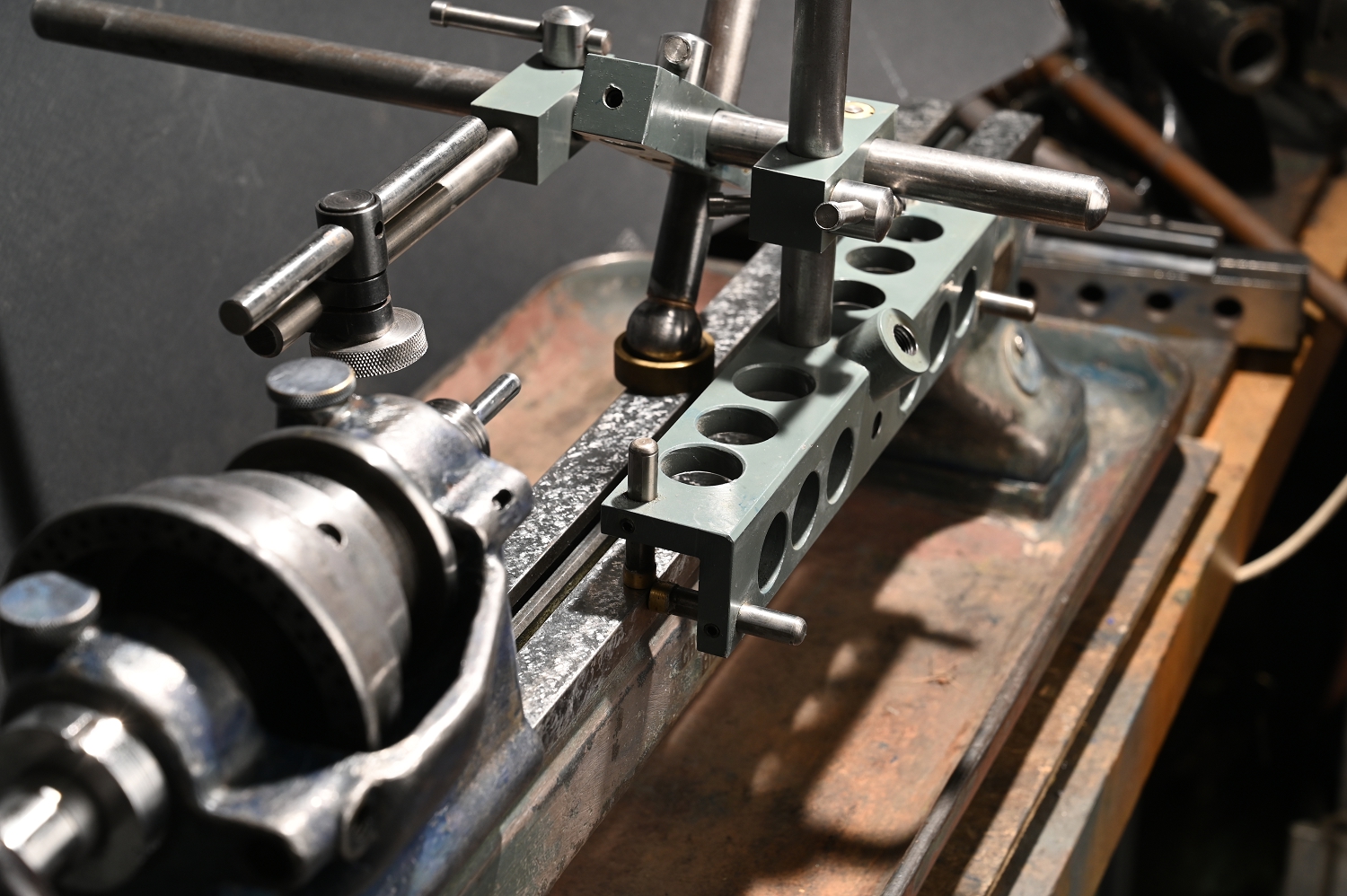
Then I checked the cross slide ways using a hastily made alignment tool. They are actually quite well aligned but I’m still planning to refinish them. With the alignment gage I got just over a thou of deviation from square. With the cross slide installed and manually moved on the ways I saw 7 tenths across the travel. The deviation is in the correct direction ie. it would face a part 10.5” in diameter 7 tenths concave.

The main reason I’d like to refinish these ways anyways is that the flats ways are not on the same plane. They are reasonably flat but one is higher than the other. Functionally this doesn’t matter when both sides are have the same difference but the upper part needs some work done to it and those surfaces not being on the same plane makes work holding difficult.
 

Attachments

  • FB7FB7B8-EA7C-4251-A4B7-7350CDE688D7.jpeg
    FB7FB7B8-EA7C-4251-A4B7-7350CDE688D7.jpeg
    492 KB · Views: 18
  • BEE19105-6E45-44AF-81E4-59BCD4333B0A.jpeg
    BEE19105-6E45-44AF-81E4-59BCD4333B0A.jpeg
    463 KB · Views: 16

Rauce

Ultra Member
I admire your patience. I'd have taken a belt sander to it by now! LOL!

But talk about a forever lathe....!

I got frustrated early on and just took it slow after that. It took a while to get a feel for how the surfaces relate to each other geometrically.

I’ve been cleaning up the last of the parts as well. The apron and the blocks that support the leadscrew/feed shaft.
 

LenVW

Process Machinery Designer
Premium Member
A good rebuild depends on TRUE datum’s and reference surfaces.
Once all your mounting points are skimmed and verified, you can be confident that the machined components will assemble to spec.
Stay with it Ross !!
 

a smile

Lifelong hobby - cold iron
Premium Member
A good rebuild depends on TRUE datum’s and reference surfaces.
Once all your mounting points are skimmed and verified, you can be confident that the machined components will assemble to spec.
Stay with it Ross !!
Ask: Is the detection of his second picture the correct combination? Can it be evaluated from a professional point of view?
 

Rauce

Ultra Member
Ask: Is the detection of his second picture the correct combination? Can it be evaluated from a professional point of view?
My tool in that photo is patterned after a tool that machine tool rebuilders have used for a long time.

@Mcgyver has a good write up on his version on his site. It’s much better than mine.

 
Top