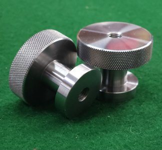
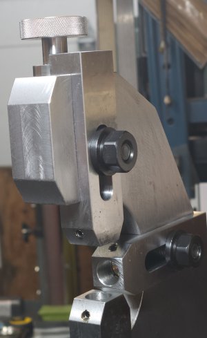
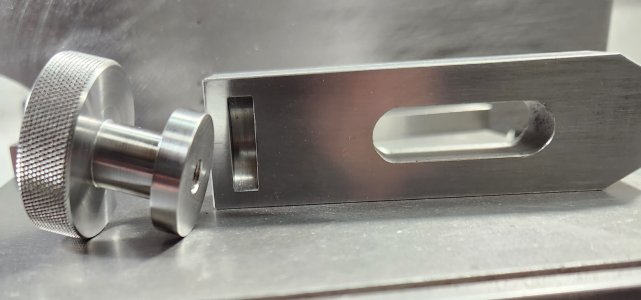
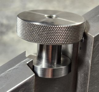
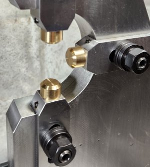
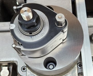
• Spring 2024 meetup in Calgary - date Saturday, April 20/2024. discussion Please RSVP Here to confirm and get your invitation and the location details. RSVP NOW so organizers can plan to get sufficient food etc. It's Tomorrow Saturday! you can still RSVP until I stop checking my phone tomorrow More info and agenda
  • We are having email/registration problems again. Diagnosis is underway. New users sorry if you are having trouble getting registered. We are exploring different options to get registered. Contact the forum via another member or on facebook if you're stuck. Update -> we think it is fixed. Let us know if not.
  • Spring meet up in Ontario, April 6/2024. NEW LOCATION See Post #31 Discussion AND THE NEW LOCATION

Follow Rest for Standard Modern

thestelster

Ultra Member
Premium Member
Very nice knurls. Accu-Trak is good stuff. Spendy at current FX but what isn't these days. What I like about that design is good mechanical advantage for applying required pressure & the tension rod comes back to operator. I posted this elsewhere but here is an online calculator for initial stock sizing using knurl DP inputs & all that stuff. I made a spreadsheet from Accu-Track formulas but the web calculator is easier & from what I can tell similar results. What I did in the past was make an table of incrementing 'optimal' diameters in a range you work in, say .5" thumbscrews to 1.5" whatever, then you have a handy shop reference to turn the stock diameter to for whatever knurl wheels you have.

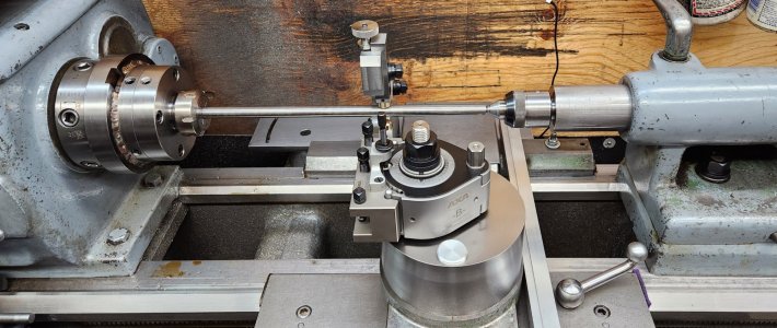
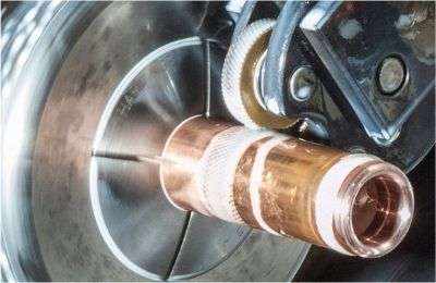
Another thing I'm considering is a constant air blow nozzle directed at the wheels/stock made from a simple bleeder line off the compressor. Re-munching the chips on certain materials is yet another reason for mucky knurls. Operating the lathe controls & knurl & directing air seems to require one more hand than I have. I bought some of this line with those quick insert connectors for another project but it might be a good way.


Hi Peter. Yes I did that as well.

The Machining doctor site is super informative. I've used the threading section often for custom threads.

I was thinking about compressor air too for knurling, but I use tons of cutting oil from a spray bottle for this application, so using air would just blow all the oil away. I don't know which would be better...oil or air?
 
Last edited:

jcdammeyer

John
Premium Member
Now to make the knobs to move the fingers in and out. Looking around the shop, I found some cutoff stainless 400 series that will work. I turned the piece down to 1.250" diameter, and decided to knurl it first before any other machining, in case the knurls don't cone out right. I'm using a Accu-Trak HD Staddle knurling tool with 96DP convex knurls.

1.250" ÷ 96 = 120 Whole number, therefore it should track properly.

Speed: 160 rpm
Feed: .015 inch/rev

-Put the knurls about 0.020" before on-center in the x-axis.
-put half the knurl on the part front edge.
-cranked the tension nut abot 1/2 turn
-engaged the feed lever
-lots of cutting oil
- started the lathe.

When it got to the far end, I DID NOT DISENGAGE THE FEED, but turned the lathe off.

Examined the knurling, and it neeted to go deeper.

-tightened the tension knob about 1/4 turn
-put the feed direction lever into L.H.
-turned on the lathe.
When it got to the begining, I DID NOT DISENGAGE THE FEED, but turned the lathe off.

Examine the knurling again, and needed to go a little deeper.

-another 1/4 turn of the tension nut, put the feed direction lever in R.H., and turned the lathe on.

Knurling is good. Loosened off the tension, spread the arms, and retracted the knurler.
Nice job. I've not yet been able to do knurls that nice. But then I couldn't do it your way anyway because my backlash is worse than the pitch of the 96 TPI knurl.
And take care of yourself. Let your body heal.
 
Last edited:

PeterT

Ultra Member
Premium Member
Those are very nice crisp knurls. All the pyramid tops are consistent points. The streets & avenues are straight lines with no other litter or potholes LOL

What material are the knobs made from?

1674501095824.png
 

thestelster

Ultra Member
Premium Member
Some more work on the follow rest today.

Affixing the knobs to the main body.

Of course, it would have been so much easier to just slot that section square instead of counterboring. But, I usually don't take the easy route.

I'm not sure I have enough clearance height on the mill to machine the vertical knob recess, so I might have to resort to using my right angle milling attachment while the body of the follow rest sits flat (on blocks) on the mill table.
 

Attachments

  • 20230129_141745.jpg
    20230129_141745.jpg
    1 MB · Views: 20
  • 20230129_141952.jpg
    20230129_141952.jpg
    279.1 KB · Views: 20
  • 20230129_142131.jpg
    20230129_142131.jpg
    449.6 KB · Views: 16
  • 20230129_142301.jpg
    20230129_142301.jpg
    225.6 KB · Views: 15
  • 20230129_151828.jpg
    20230129_151828.jpg
    460 KB · Views: 15
  • 20230129_152044.jpg
    20230129_152044.jpg
    274.9 KB · Views: 19

thestelster

Ultra Member
Premium Member
I just received the bronze rods which will be used to make the contact tips of the follower fingers.

The one rod is C93200 (SAE660) Leaded tin bronze.

The other rod is C95400 Aluminium bronze.
 

Attachments

  • 20230131_152950.jpg
    20230131_152950.jpg
    304.8 KB · Views: 4

PeterT

Ultra Member
Premium Member
I haven't machined aluminum bronze yet, but have C93200. I actually like working with it, but it has some characteristics similar to brass. Larger diameter drills can be grabby & benefit by dubbed rake profile. OD turning is pretty straightforward, I like the same sharp uncoated inserts as used on aluminum. If you have to set bronze parts using Loctite retainer, be aware it sets off quite a bit faster relative to other conventional alloys.
 

thestelster

Ultra Member
Premium Member
I haven't machined aluminum bronze yet, but have C93200. I actually like working with it, but it has some characteristics similar to brass. Larger diameter drills can be grabby & benefit by dubbed rake profile. OD turning is pretty straightforward, I like the same sharp uncoated inserts as used on aluminum. If you have to set bronze parts using Loctite retainer, be aware it sets off quite a bit faster relative to other conventional alloys.
Thank you Peter.
 

thestelster

Ultra Member
Premium Member
Slowly but surely. The finger tips using C95400 Aluminium Bronze.

I had the table almost to the very bottom, and still not enough clearance for a drill chuck. Had to use collets to hold the drill bits.

There is still a ways to go yet.
 

Attachments

  • 20230201_154229.jpg
    20230201_154229.jpg
    518.2 KB · Views: 24
  • 20230201_192059.jpg
    20230201_192059.jpg
    313.2 KB · Views: 24
  • 20230201_192113.jpg
    20230201_192113.jpg
    356.3 KB · Views: 25

thestelster

Ultra Member
Premium Member
Some adjustments had to be made. Previously, I removed my compound slide and incorporated a solid toolpost plinth. With the position of the QCTP, the cutting tool insert edge was forward of the traveling steady fingers by 1". I was thinking that's too much.
Luckily when I was machining the solid plinth, I decided to position the bolt for the QCTP off-center. So by rotating the plinth on cross-slide I was able to reduce the gap between cutting edge and traveling steady finger tips to 1/4". And, if i wanted to, i can continue to rotate the plynth so that the cutter would be behind the fingers.

The other issue is that the tailstock center has to stick out too far. This is because of the way I've attached the X-axis DRO scale reader. I'll try to modify it at a later date.
 

Attachments

  • 20230202_144523.jpg
    20230202_144523.jpg
    388 KB · Views: 16
  • 20230202_144559.jpg
    20230202_144559.jpg
    644.9 KB · Views: 16
  • 20230202_144957.jpg
    20230202_144957.jpg
    633.4 KB · Views: 13
  • 20230202_145305.jpg
    20230202_145305.jpg
    492.7 KB · Views: 13
  • 20230202_155948.jpg
    20230202_155948.jpg
    485.9 KB · Views: 16

thestelster

Ultra Member
Premium Member
I did a test run. The material is 5/8" cold rolled. Held in the collet chuck and live center.
-turned length is 14"
-speed: 670 rpm
-depth of cut 0.020", @0.005"/rev. feed
-DCGX carbide insert (for Aluminum uncoated) I figured lets try this: sharp, very positive, low cutting forces.
-squirting oil at the finger tips
-only used the top and x-axis fingers

Results:
-It cut a taper of 0.002" total over the whole length, (smaller at the tail stock.
-runout @head: 0.0003"
-runout @midpoint: 0.004"
-runout @tail: 0.001"
#runout of live center at the conical section is 0.001", while the cylindrical section is 0.0002". Hmmm...I guess I have to grind that secion true.
-no wavyness, though it looks as if everytime the chip broke off from the material it left a slight ridge app. 3-4 tenths. But not evenly spaced along the material. Some chips were short others were quite long.

I'm going to experiment more today and try to get better results.
ie
-adjust tailstock
-contour the finger tips
-utilize the bottom finger
-maybe try different inserts or HSS tool
 

Attachments

  • 20230202_161200.jpg
    20230202_161200.jpg
    290.6 KB · Views: 5

Mcgyver

Ultra Member
I've found that it takes a bit of touch and experience to get things really parallel. The fingers need to deliver a slightly different force in the middle than the do at the tailstock where the centre is supporting things. After a few passes I would know how far after the tailstock, and with what force, to bring the fingers into contact with the work. Its not a tidbit you find written down in too many places, but it lets you really make it sing.
 
Top