Hi Craig, yes it will be all out of steel. But, the percentage improvements by design modifications will (possibly) translate into the final assembly as well.Why are you measuring the deflection of the wood mock up? You're making the final product from steel plate are you not?
-
Scam Alert. Members are reminded to NOT send money to buy anything. Don't buy things remote and have it shipped - go get it yourself, pay in person, and take your equipment with you. Scammers have burned people on this forum. Urgency, secrecy, excuses, selling for friend, newish members, FUD, are RED FLAGS. A video conference call is not adequate assurance. Face to face interactions are required. Please report suspicions to the forum admins. Stay Safe - anyone can get scammed.
-
Several Regions have held meetups already, but others are being planned or are evaluating the interest. The Calgary Area Meetup is set for Saturday July 12th at 10am. The signup thread is here! Arbutus has also explored interest in a Fraser Valley meetup but it seems members either missed his thread or had other plans. Let him know if you are interested in a meetup later in the year by posting here! Slowpoke is trying to pull together an Ottawa area meetup later this summer. No date has been selected yet, so let him know if you are interested here! We are not aware of any other meetups being planned this year. If you are interested in doing something in your area, let everyone know and make it happen! Meetups are a great way to make new machining friends and get hands on help in your area. Don’t be shy, sign up and come, or plan your own meetup!
You are using an out of date browser. It may not display this or other websites correctly.
You should upgrade or use an alternative browser.
You should upgrade or use an alternative browser.
Follow Rest for Standard Modern
- Thread starter thestelster
- Start date
That's kind of what my right angle plate idea was also trying to address. However it only works if you have T slots in the cross slide (which thankfully I do have).
The typical follow rest are robust chunks of CI, no issue there. But the whole system relies on 2 bolts screwed horizontally into cross slide. Supposedly it should stay tight & secure but the cutting force is acting to rotate the steady body against these bolts.... Anyways I figure if I had to make one, an adjoining integral right angle plate, bolted vertically into the T's would provide better support. And if one designed it right, ideally allow for different mount positions. I want to make myself a micro version for turning very thin aspect ratio stock.
The typical follow rest are robust chunks of CI, no issue there. But the whole system relies on 2 bolts screwed horizontally into cross slide. Supposedly it should stay tight & secure but the cutting force is acting to rotate the steady body against these bolts.... Anyways I figure if I had to make one, an adjoining integral right angle plate, bolted vertically into the T's would provide better support. And if one designed it right, ideally allow for different mount positions. I want to make myself a micro version for turning very thin aspect ratio stock.
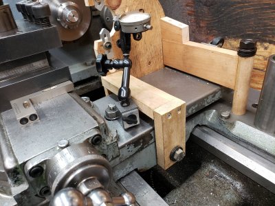
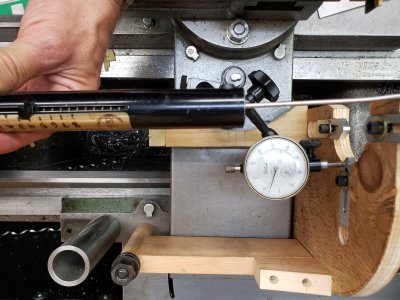
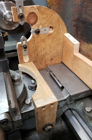
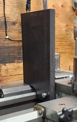
There seemed to still be too much flex. So, version 4 &5.
Version 4 had 0.005" deflection, but then I couldn't move the cross-slide close enough, so I had to cut out some sections. Saying that, deflection is at 0.006".
Version 4 had 0.005" deflection, but then I couldn't move the cross-slide close enough, so I had to cut out some sections. Saying that, deflection is at 0.006".
Attachments
Why are you measuring the deflection of the wood mock up? You're making the final product from steel plate are you not?
While wood can be quite non-homogenous, it's still a good proxy. The numbers will usually scale and its easy enough to modify. The shape is what can drive you nuts by distorting in places you didn't expect.
I like @thestelster s approach to this. He will learn a lot by playing with a wooden prototype before committing to machining a piece of steel. But ya, the final steel part won't deform like the wood does. However it will be a much better final result than it would have been by going straight to steel.
But the whole system relies on 2 bolts screwed horizontally into cross slide.
Right on @PeterT! This is EXACTLY what always bothered me about my follow rest! No design is ever better than its weakest link.
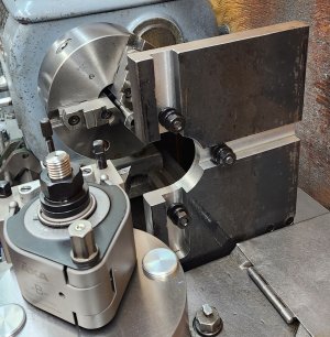
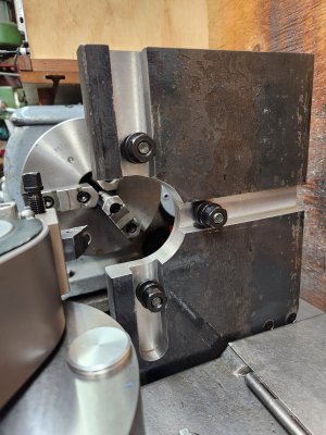
I started making the follow rest the other day. I'm planning on using the basic design as my wood mock-up, plus suggestions from our members.
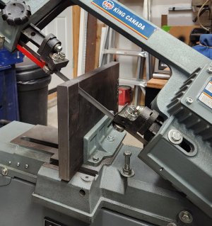
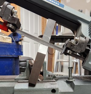
The frame is a 1" thick piece of hot rolled steel slab.
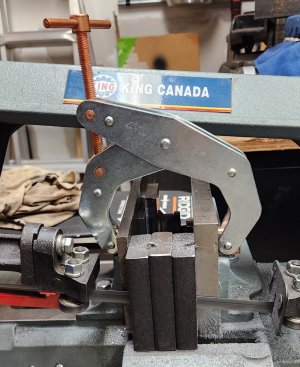
Started on the bandsaw, of course this piece is pretty big for the saw, do had to clamp it on an angle.
The frame is a 1" thick piece of hot rolled steel slab.
Started on the bandsaw, of course this piece is pretty big for the saw, do had to clamp it on an angle.
Attachments
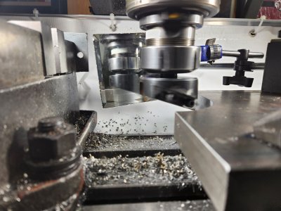
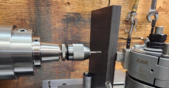
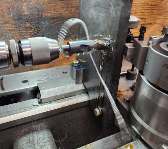
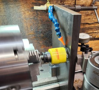
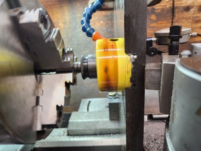
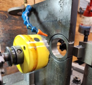
Now to make the hole. 3", in diameter. I don't have annular cutters, so this took a little while. Spot drill, 1/4" drill, 1/2", 1". I switched from the 5C collet chuck, to the three jaw, because there was going to be a lot of torque when using the 3" hole saw.
I started with a 2 1/4" hole saw, just to see if that would work. It was really slow going. .020" pecks, because the teeth were getting clogged, even with compressed air or cutting fluid. Perhaps if I had high pressure flood cooling it would work, but I don't.
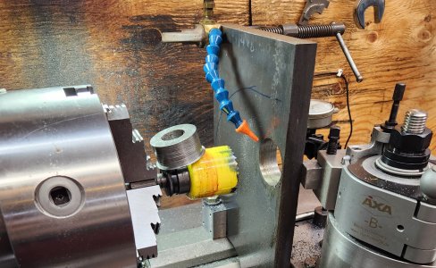
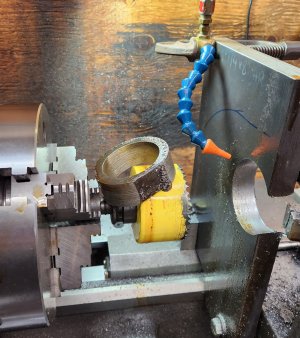
Then switched to the 3" holesaw. Much trepidation since not all the teeth would be engaged in the material.
I needn't have worried, it actually allowed the chips to evacute the cut and it went very quickly with power feed.
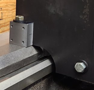
I also used the QCTP to hold a hunk of steel to support the slab from flexing.
Attachments
Now to make the hole. 3", in diameter. I don't have annular cutters, so this took a little while. .
Then switched to the 3" holesaw. Much trepidation since not all the teeth would be engaged in the material.
I would have ordered an annular cutter...... Most of them that I have seen use a 3/4" Weldon Shank.
Another alternative would be a boring bar mounted in the chuck with an axial bit to use like reverse trepanning.
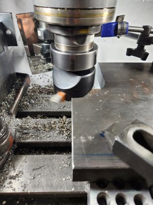
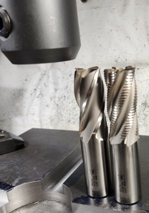
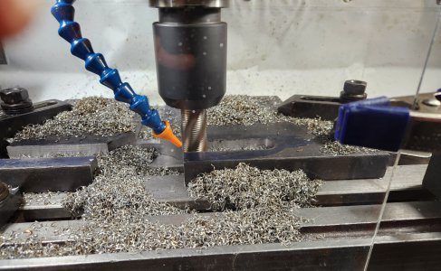
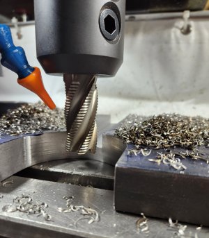
Making the slots for the support fingers. 1" wide, 1/2" depth. First using a 1" HSS roughing endmill. 0.400" depth cut (I should have taken the whole .5", it cut so nicely). 350rpm @ ~3ipm. Then used the finish endmill to clean up the sides.
Attachments
Annular cutters are on my wish list! But, honestly, if I had gone straight to the 3" holesaw, I would have been done in 5minutes!! Having the holesaw off the side of the material, clearing all the shavings made quick work!I would have ordered an annular cutter...... Most of them that I have seen use a 3/4" Weldon Shank.
Another alternative would be a boring bar mounted in the chuck with an axial bit to use like reverse trepanning.
Former Member
Guest
If you are looking to add stiffness without bulk or wt (lots) add a flat bar to make it "T" shape to the top/back edge. Taper in width wise to from the nose (no bending moment here) to further back and down (maximum bending moment here).
Lets you avoid interference issues yet have the performance you want.
Lets you avoid interference issues yet have the performance you want.
Thank you. My intent is to stiffen it up, but I havent decided on the final shape of the follow rest. I would like to make the rear section in an arc, and I don't think it will compromise the rigidity. Plus I have to take into consideration the placement of the x-axis scale, taper-turning attachment, tailstock, and QCTP.If you are looking to add stiffness without bulk or wt (lots) add a flat bar to make it "T" shape to the top/back edge. Taper in width wise to from the nose (no bending moment here) to further back and down (maximum bending moment here).
Lets you avoid interference issues yet have the performance you want.
I now have to make the support fingers. I've been trying to decide what best material to make them from, and I've been scouring the internet to find an answer. And the consensus is....it depends! Of course!
Bronze, cast iron, hardened steel, carbide, Teflon.....
Maybe make a set with removable pads of the different materials.
HELP!!! Any advice will be most appreciated.
Bronze, cast iron, hardened steel, carbide, Teflon.....
Maybe make a set with removable pads of the different materials.
HELP!!! Any advice will be most appreciated.
I now have to make the support fingers. I've been trying to decide what best material to make them from, and I've been scouring the internet to find an answer. And the consensus is....it depends! Of course!
Bronze, cast iron, hardened steel, carbide, Teflon.....
Maybe make a set with removable pads of the different materials.
HELP!!! Any advice will be most appreciated.
Make the ones you think you will use the most, you can always make multiple sets of different materials
Are bronze fingers not the most common that come with factory made rests? That's probabaly what I would go with unless you had some specific reason for another material type
Yes, bronze seems to be the multi-pupose material, but at almost $200 worth of material needed, it's a little dear. That's why I'm contemplating steel fingers, with replaceable tips.Make the ones you think you will use the most, you can always make multiple sets of different materials
Are bronze fingers not the most common that come with factory made rests? That's probabaly what I would go with unless you had some specific reason for another material type
Seems like depending on supplier there is more bronze alloy selection in round vs rectangular. But it might be spendy to make the whole finger out of bronze when only the tip is in contact.
Most of the replaceable tips I see are integrated into round fingers with kind of a tenon boss into a hole in the finger. But assume your fingers are rectangular? Show us what you have in mind. I'm sure there is a viable method, just have to figure out the most viable.
 www.onlinemetals.com
Most of the replaceable tips I see are integrated into round fingers with kind of a tenon boss into a hole in the finger. But assume your fingers are rectangular? Show us what you have in mind. I'm sure there is a viable method, just have to figure out the most viable.
Buy Bronze Cut to Size - Price and Order | Online Metals
Online Metals offers bronze in various shapes and alloys - available in standard and custom lengths. Price your order and purchase online - no minimums.
Attachments
HELP!!! Any advice will be most appreciated.
Roller Bearings?
Exactly!But it might be spendy to make the whole finger out of bronze when only the tip is in contact.
Yes, rectangular.
I'm not sure of attachment yet, Threaded, dovetail, pin, securing screw. I'm making the finger bodies now, and I'll think it through as I make them, and get suggestions.

