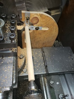
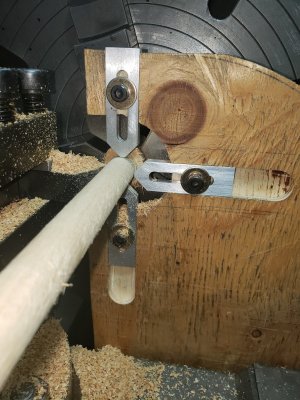
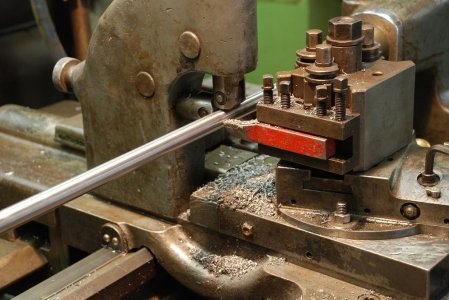
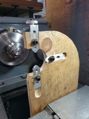
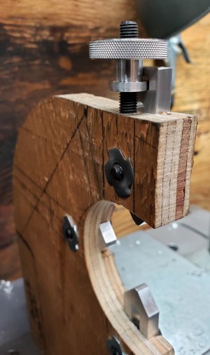
I'm in the early stages of making a follow rest for my lathe. I've got a headache reading and viewing posts, images, and videos. So here goes. I made a mock up from plywood and aluminium fingers/jaws. The capacity is 2.5". I decided to go with a three finger set up. I read somewhere where it was better for small OD's. I plan on making it out of HR low alloy steel and bronze jaws. Its held in place with two 1/2"-13 bolts. 1 going into the side of the saddle, and the other on top. The threaded holes were already there. As you can see, I tried it out on a piece of 1" wood dowel, the turned section is 9" long. It worked way better than I thought it would. . Any advice would be really appreciated.
-
Spring 2024 meetup in Calgary - date Saturday, April 20/2024. discussion Please RSVP Here to confirm and get your invitation and the location details. RSVP NOW so organizers can plan to get sufficient food etc. One week to go! More info and agenda
-
We are having email/registration problems again. Diagnosis is underway. New users sorry if you are having trouble getting registered. We are exploring different options to get registered. Contact the forum via another member or on facebook if you're stuck. Update -> we think it is fixed. Let us know if not.
You are using an out of date browser. It may not display this or other websites correctly.
You should upgrade or use an alternative browser.
You should upgrade or use an alternative browser.
Follow Rest for Standard Modern
- Thread starter thestelster
- Start date
9" Utilathe Follower Rest
The final thing I'm missing to complete my 9" Utilathe is a Follower Rest. I've been pondering this for months now and spotting a $500US used SM follower on Ebay finally prompted me to make one. @Brent H posted plans for one here 9” and 10” Utilathe Follow Rest Plans | Canadian Hobby Metal...
Hi David, thank you. I just watched it. Great idea for super small diameters.Joe Pi made an impromptu follow-rest that could provide some inspiration.
Hi Craig. Thank you. I'll have read the whole post later today. I did see that design for the smaller Standard Moderns, but it appeared to me that the FR fingers would be right in the middle of my compound. My tool post is so large I'd have to have it hanging off the end. I think that style was originally for the lantern type tool posts. I saw one guy who had the jaw section dovetailed so you could move the whole thing left or right.
9" Utilathe Follower Rest
The final thing I'm missing to complete my 9" Utilathe is a Follower Rest. I've been pondering this for months now and spotting a $500US used SM follower on Ebay finally prompted me to make one. @Brent H posted plans for one here 9” and 10” Utilathe Follow Rest Plans | Canadian Hobby Metal...canadianhobbymetalworkers.com
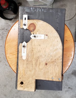
Well, I finally went and got the steel to make the follow-rest for my Standard Modern 1654 Utilathe. I think I will incorporate 3 jaws. I was hoping I can get some input from those who have used a follow rest as to what design features they wish were incorporated in their design. And if anyone has photos or drawings from companies like Monarch, Schaublin, Hardinge, etc, it would be greatly appreciated.
Attachments
Follow rest and steady are on the list to build for my lathe
From my research it seems to not really matter what it looks like, all the home/shop built ones looks different, so just make it to suit what are plan on doing with it
The only thing I can really note is that a follow rest usually only has 2 fingers kind of in the 12/3 position, the 6 position is redundant, the piece is trying to climb up + back in a conventional cut anyways
I'll be following along. My DRO bracket assembly is occupying the space (in fact the mounting holes) normally intended for travel steady. That was kind of a known compromise when I installed DRO. I do have T slots in my cross slide so I was thinking of a right angle plate type setup. I haven't mocked it up yet, so might be hair brained.
Attachments
Hmnn that seems like a good suction to me Peter. I have a dro to install on a lathe and I was avoiding the front carriage mounting postion for the scale for that very reason. Now I need to rethink that given your possible solution. The only issue I can immediately think of is that my OEM travel steady won't work because of height differences.I'll be following along. My DRO bracket assembly is occupying the space (in fact the mounting holes) normally intended for travel steady. That was kind of a known compromise when I installed DRO. I do have T slots in my cross slide so I was thinking of a right angle plate type setup. I haven't mocked it up yet, so might be hair brained.
Not saying you need any or all of this to make a good go of it, but here's a few ideas and observations and what I learned about them.
Note in each case they made an effort to the get support to about the middle of cross slide. This lets you position support behind the cut. that's what you need; then support is on a true round surface which is true because of the tail stock support.
I found bringing the fingers in after the cut has started was neccessary to get accurate results....to soon and you up small OD at the end. you'd get too much support with finger and TS. Support is really only needed once the cut gets away from tailstock - having the fingers infeed by a screw is a huge advantage....lets you bring into contact as everything is moving and with a bit of practice judge just right amount of torque then clamp them down. You can hold a thou or two over several feet this way.
Photo of a SM travelling steady from I think it was a 12" I had years ago. Not rigid enough imo, there's a moment created around where it bolts to the cross slide....your design with the web along the X axis is superior imo.
Next photo is of one for a 10ee. Lousy photo, but I sold that lathe and was just trying to display what came with it. Note the offset and support in the Z axis as well.
Last bunch pics are of the one from my DSG. All others are second fiddle. Just massive box casting and a pleasure to use. It clamps to the dovetail. It came with roller bearings on the fingers. I found even with brand new bearings, it takes a bit of force to get them turning and that force affects the dimension. Bronze imo is more accurate and more sensitive so I made a set. In the photo is a feedscrew being made and it was kept to with .002 pitch diameter over its length....for threading that is really exact. the only way I could think of to do was to bring the fingers in after things got away from the TS making the DSG style infeeds on the fingers a nice feature.
Also note, everyone only has 2 fingers, one the X and one vertical....that's the direction of the forces
.JPG")


Attachments
Last edited:
I like what @Mcgyver says. Note how much fatter his steady is so he can use cylindrical follow roller assemblies.
I'm not sure the whole body needs to be so fat though. Just where the cylindrical rollers are.
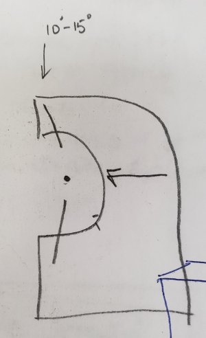
Also, it seems to me that a little bit more meat at the top would help manage the distortion and therefore vibration under heavier cutting loads. This might be hard to explain in words, but I'm in bed so no quick drawings tonight. The vertical cross section should increase as you get further from the top nose. The two plywood models you guys both posted have a top finger with a relatively constant cross section. It would be better if it were taller as you get further away from the nose to increase the cross section as the loads go up due to the leverage at the top roller.
I'm not sure the whole body needs to be so fat though. Just where the cylindrical rollers are.
Also, it seems to me that a little bit more meat at the top would help manage the distortion and therefore vibration under heavier cutting loads. This might be hard to explain in words, but I'm in bed so no quick drawings tonight. The vertical cross section should increase as you get further from the top nose. The two plywood models you guys both posted have a top finger with a relatively constant cross section. It would be better if it were taller as you get further away from the nose to increase the cross section as the loads go up due to the leverage at the top roller.
@Mcgyver
@Susquatch
Have a read of the link below at the Practical Machinist site regarding follow rests:
https://www.practicalmachinist.com/forum/threads/follow-rest-design-options.189421/
They discuss the three jaw follow rests, as well as having them at differing positions (in regards to the clock face).
@Susquatch
Have a read of the link below at the Practical Machinist site regarding follow rests:
https://www.practicalmachinist.com/forum/threads/follow-rest-design-options.189421/
They discuss the three jaw follow rests, as well as having them at differing positions (in regards to the clock face).
What I was trying to say earlier about increasing the nose section. This would yield a significant increase in stiffness at the top roller.

That shouldn't be a problem. The steel plate that I bought is 4" longer, so I will definitely beef up that area.What I was trying to say earlier about increasing the nose section. This would yield a significant increase in stiffness at the top roller.
View attachment 25090
That shouldn't be a problem. The steel plate that I bought is 4" longer, so I will definitely beef up that area.
Are you planning to use rollers or noses? Do you have the parts for that yet?
I'm planning on bronze or brass jaws. Not sure which is most suitable. Or maybe steel jaws with replaceable bronze/brass noses.Are you planning to use rollers or noses? Do you have the parts for that yet?
I'm planning on bronze or brass jaws. Not sure which is most suitable. Or maybe steel jaws with replaceable bronze/brass noses.
Bronze is better. It has much higher lubricity than brass. Some bronze alloys are better than others though. But I forget which alloy is best. I'd do replaceable noses in steel if it were me.
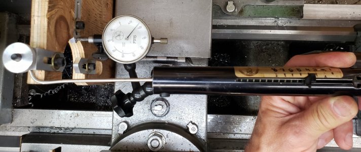
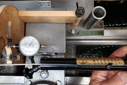
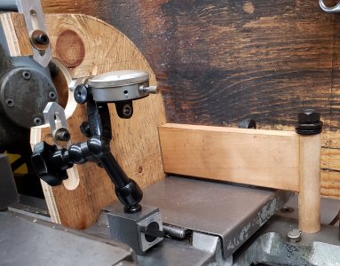
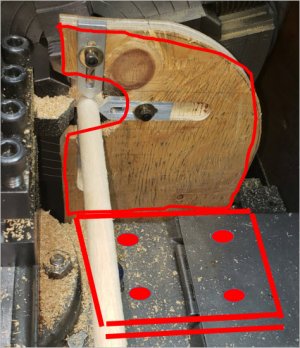
I decided to beef up the design by adopting a support arm. The deflection without the support arm and a 4lb force is 0.018". With the support arm it's 0.012". Therefore app. 33% less deflection. I think if the arm was more of a triangle vs. rectangle, and taller at the main follow rest plate, it would be considerably stiffer.