Cross-Slide Leadscrew & Nut

PeterT

Ultra Member
Premium Member
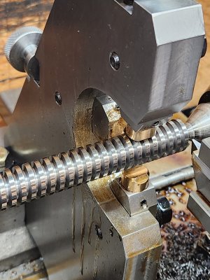
Its worth making a new nut because a) looks like you need one anyways b) you will be able to better quantify your leadscrew wear c) its less work. Thread the nut to position X, pull forth & back, measure backlash with DTI, move to next position X, rinse & repeat. Compare to your existing worn nut. You may find negligible wear or you may find localized wear but either way be in a better position to assess if you can run the leadscrew as-is or make another.

I saw a guy splice a new leadscrew threaded segment using a donor section from his existing screw, but if I recall, it had some funky threads or splines he was not in a proper position to replicate. But yours looks more straightforward. Or make a new one & flog your existing one on Ebay, there are always people looking for plug-n-play.
 

Darren

Ultra Member
Premium Member
A thought that also occurred to me, it would it be a reasonable repair to 'correct' your existing screw, even if it means that it's a non standard size. You're making a new nut so it really doesn't matter if it is an oddball pitch diameter.
 

PeterT

Ultra Member
Premium Member
From everything I've read, and what I measured on my own, the leadscrew wear occurs along the tapered surface of the screw. Maybe more one side or the other depending on ABL nut type but Id expect predominantly the opposite side of infeed load. But the PITA aspect of remedial work is wear is usually over a localized segment of the screw corresponding to its highest use, a function of most common part diameter range. That means pitch diameter will be smaller there & return to 'spec' outside the range. So even if you had a nice fitting nut in the wear range, it would be relatively tight in the less-wear range. I guess you could re-machine the thread so its all uniform smaller PD but now you are into thread chasing fun & dealing with teeny amounts of infeed and a custom nut. Somewhere I have a table of fits but I seem to recall the PD deviation for leadscrew class fits was pretty narrow & within that spec is what the ABL fine tuning is supposed to take up.
 

thestelster

Ultra Member
Premium Member
Well, after some deliberation, I've decided to make a new feed screw. What the heck, eh, it'll be a learning experience.

I decided to make threads on a short section of the same material, 1144 Stressproof. Chucked it in the 3-jaw, runout was about a thou'. Center drilled for a live center, and set everything up. Set the compound to 14.5°, calculated what the compound feed needed to be to get the proper depth.

Now, my crossfeed screw is 5tpi, but the threading tool I made was about a 6tpi. In this manner I could get to the proper pitch diameter while keeping the maximum minor diameter.

Started threading and got to the proper depth, but the cutter was raising a burr on the leading edge and I noticed that it was rubbing a bit. You can see it in one of the pictures. Obviously I didn't grind enough side clearance.

Once at proper depth, I rotated the compound to allow the cutter to move axially, (parallel to the bed ways). And then relocated the cutter into one of the threads by moving the compound in or out ( in this case left or right). Zeroed everything, test run, all good. Moved the compound to the right 0.005", and started to thread. Hmmm, no chips. Ok, do it again, move another 0.005", still nothing. Something is wrong. Then I noticed my threading tool had moved. I guess because there wasn't enough side clearance it was creating a lot of axially forces against the cutter, and because we're doing a left hand thread, the cutter isn't supported in the tool holder.

So I took out the cutter, and reground the right side for 8° of clearance. Put everything back, and started again. And success. No burrs. And kept moving the compond until I got the proper pitch diameter.
 

Attachments

  • 20240304_120625.jpg
    20240304_120625.jpg
    490 KB · Views: 22
  • IMG_20240304_125830.jpg
    IMG_20240304_125830.jpg
    426 KB · Views: 20
  • 20240304_125926.jpg
    20240304_125926.jpg
    636.5 KB · Views: 19
  • IMG_20240304_131343.jpg
    IMG_20240304_131343.jpg
    218.5 KB · Views: 20
  • 20240304_181439.jpg
    20240304_181439.jpg
    365.8 KB · Views: 22

PeterT

Ultra Member
Premium Member
Nice threads! But I'm not quite following you. You are modifying what was a 6-TPI cutter to what ultimately will cut 5-TPI on the replacement screw?

At some point I want to better understand the 3D faceted thread form for both external & internal cutters. It occurs to me I should be able to draw it up & turn that into an angle recipe for cutting the form using the work head of tool cutting grinder. Just need to figure out how to hold square stock in a round collet.
 

Susquatch

Ultra Member
Administrator
Moderator
Premium Member
At some point I want to better understand the 3D faceted thread form for both external & internal cutters. It occurs to me I should be able to draw it up & turn that into an angle recipe for cutting the form using the work head of tool cutting grinder.

I really have no idea what you are asking here. I like that about you. You make me think.....

Just need to figure out how to hold square stock in a round collet.

So this is a whacky idea. I'm just putting it out there to stimulate discussion.

I assume you don't have square collets. I don't either.

Clamp some flat aluminium stock to your square stock with a hose clamp and put the whole thing in a four jaw to center the bar stock and then turn the flat stock till its round and fits the appropriate collet. Then take it out of the 4 jaw and put it into the collet.

Hope that kicks off better ideas.
 

thestelster

Ultra Member
Premium Member
You are modifying what was a 6-TPI cutter to what ultimately will cut 5-TPI on the replacement screw?
I ground the acme thread tool from a blank piece of 3/8"HSS.

The basic thread form of acme, (or most other thread forms), have the same dimensions, whether the tool or insert is 1 tpi or 32tpi, with the exception of the tip of the cutter. The former will have a much larger tip than the latter. So in reality you can use a 32tpi tool to cut 1 tpi thread, only if that tool is deep enough. You can't do the reverse. That's exactly what's available for carbide threading inserts. You have full form (topping) inserts which are only designed for a specific thread pitch, or you have non-topping inserts which can be used to do many different pitches.

But if you use a non-topping tool, say that is designed for thread pitches between 12-32tpi. You will notice that the tip of that insert is very pointy. This allows you to cut the proper root dimension for 32tpi, but too small for 12tpi. Therefore you either go deeper with the threading tool, or move axially to widen the root to get you to the proper pitch diameter.

I prefer using non-topping inserts, because it allows me to reduce my inventory of threading inserts, and allows me total control of the root and pitch dimensions.

But if you have a solid tool post (no compound), you have to use full form topping inserts (or Electronic Lead Screw).

So that's basically what I've done with the acme tool I made. I can cut acme threads from 6tpi-1tpi. I just have to move the compound axially to widen the thread to give me the correct pitch diameter for a given thread pitch.
 

Susquatch

Ultra Member
Administrator
Moderator
Premium Member
Nice threads! But I'm not quite following you. You are modifying what was a 6-TPI cutter to what ultimately will cut 5-TPI on the replacement screw?

I think what @thestelster is trying to say is that he is using a 6tpi form tool to cut a 5tpi thread and then runs the tool laterally to expand the thread groove until it is the right form for a 5tpi thread.
 

PeterT

Ultra Member
Premium Member
I might be off in my own universe until I think this through. I was trying to say that varying the pitch would also require varying the threading tool back clearance beneath the oblique thread profile on that basis alone in order to advance the cut without interference & maybe that's what @thestelster was doing by modifying his tool. Sounds like that is not what he is doing but I'm having trouble quantifying the minimum facet plane of the tool so I must be doing something wrong. TBC. I need to dig out the Handbook. I'm even starting to become suspect of some of the YouTube thread CAD videos.

1709692319052.png
 

PeterT

Ultra Member
Premium Member
I assume you don't have square collets. I don't either. Clamp some flat aluminium stock to your square stock with a hose clamp and put the whole thing in a four jaw to center the bar stock and then turn the flat stock till its round and fits the appropriate collet. Then take it out of the 4 jaw and put it into the collet.

No, I don't have square collets. They make 5C & *I think* also R8 but not as common. I'm not really keen to splurge. But yes, making some kind of a cylindrical based holding fixture is probably the way to go. Anyways a TCG work head has the types of motion & infeed required to make a nice Vee cutter profiles of any required included angle, including back relief & nose profile features (he says confidently with very little actual time on the beast). That's the point I want to get to eventually. Grainy internet picture but hopefully conveys the multi-axis geometry.

1709693247179.png
 

thestelster

Ultra Member
Premium Member
that varying the pitch would also require varying the threading tool back clearance
Yes, the thread lead angle will vary depending on the pitch, but also diameter. In the link below, it explains it breifly and provides a calculator. So I pluged in my dimensions, 0.750" and 5tpi into the calculator, and it gives me an angle of 4.8°, so I ground the leading edge of my tool to 8° to provide enough clearance, and kept the trailing side at 4° (so now this tool is only for left hand acme threads. Though. I could grind the other side to 8°as well).


Susquatch

Ultra Member
Administrator
Moderator
Premium Member
I might be off in my own universe until I think this through. I was trying to say that varying the pitch would also require varying the threading tool back clearance beneath the oblique thread profile on that basis alone in order to advance the cut without interference & maybe that's what @thestelster was doing by modifying his tool. Sounds like that is not what he is doing but I'm having trouble quantifying the minimum facet plane of the tool so I must be doing something wrong. TBC. I need to dig out the Handbook. I'm even starting to become suspect of some of the YouTube thread CAD videos.

View attachment 45156

I'm not sure what you are saying Peter. The red plane in your drawing is just a big huge question mark in my head. It doesn't appear to represent anything. It doesn't even look like it is on a right angle to the cylinder axis itself. I do love the light green thread indicator toroid though.

Hopefully what @thestelster said above explains what he is doing and why though.
 

RobinHood

Ultra Member
Premium Member
The red plane in your drawing is just a big huge question mark in my head. It doesn't appear to represent anything.
I think Peter is showing a section of the “helix plane”. One can use it to measure the helix angle when referenced to the normal axis.

It’s basically like a section of flighting on an auger.

IMG_2607.jpeg
 

Susquatch

Ultra Member
Administrator
Moderator
Premium Member
It’s basically like a section of flighting on an auger.

That's what I originally thought too. But these two markups don't support that. A plane on the Helix would stay on the helix and wouldn't intercept it as shown below with A.

Screenshot_20240306_120732_Chrome.jpg

Furthermore, a construction plane to show the helix angle would be at a right angle the to the shaft axis, and this one isn't as shown by a line that is in B.

What would be interesting is to see that plane on edge so its a line. Perhaps then I could see where it is and what it represents.

Screenshot_20240306_120759_Chrome.jpg
 

thestelster

Ultra Member
Premium Member
Couldn't do much today. Had to tend to the parental units.

But, I think I'm ready to start the actual crossfeed screw. I'll do the acme threads first. I cut 24" of some 3/4" 1144 Stressproof. Faced, center drilled, and chamfered both ends. Set the compound to 14.5°. Set the cutter perpendicular to shaft, checked tool height. Attached follow rest, and made sure I had enough room at the start and the end.

To be continued tomorrow. I'm going to go work out.
 

Attachments

  • 20240306_170953.jpg
    20240306_170953.jpg
    483 KB · Views: 13
  • 20240306_171247.jpg
    20240306_171247.jpg
    553.9 KB · Views: 13

PeterT

Ultra Member
Premium Member
Its hard to make sense of the red plane in isolation like that. But where I was wanting to go with it is: constrain plane coincident to the leading edge of the thread profile (shown in half section of the screw = the edge of the cutting tool on center) & also tangent to thread flank which will be at some angle.. as a basis for what the minimum tool back relief must exceed (roughly sketched in orange). If you imagine a deep say rectangular cutting tool with only the Vee angle profiled obliquely (no relief), its easy to imagine it could interfere with underlying threads somewhere. So we would grind some relief in to some amount, which I think is a function of thread pitch, thread depth & tool body dimensions. Thats what I mistakenly thought @thestelster was doing but obviously misunderstood. Anyway, I'm not quite there yet but I think I know what I did wrong. Probably not solving any problems that aren't in a handbook somewhere, but I've been wanting a generic CAD threading workflow where I can specify any type of thread, internal or external, on any kind of surface & it gives me useful information.
 

Attachments

  • EDT-06-03-2024 5.40.08 PM.jpg
    EDT-06-03-2024 5.40.08 PM.jpg
    69.1 KB · Views: 4

mmcmdl

Machinist/Toolmaker ( retired )
@thestelster Easy way to chase those Acmes with a lot less pressure . Thread the bar with a regular 60 degree insert undersize and rethread it with your Acme tool . A lot less pressure is exerted on the finish tool . I used to do this on the CNCs years back that didn't have the torque for the course Acmes . Just a thought if you run into issues .
 

thestelster

Ultra Member
Premium Member
@thestelster Easy way to chase those Acmes with a lot less pressure . Thread the bar with a regular 60 degree insert undersize and rethread it with your Acme tool . A lot less pressure is exerted on the finish tool . I used to do this on the CNCs years back that didn't have the torque for the course Acmes . Just a thought if you run into issues .
When I did the test run a couple days ago, once I increased the side clearance of the leading edge of the threading bit to 8°, it cut well. That was another reason I used a 6tpi (actually its closer to a 7tpi), instead of the 5tpi that I needed. The nose of the cutter being thinner, there was less resistive forces involved.
 

thestelster

Ultra Member
Premium Member
A little more work on the crossfeed screw today. We're now at the proper depth, 0.530" 5tpi, moving in at 14.5°. Tomorrow I will set the compound to be parallel with the lathe ways, and widen the thread by moving the compound until we get the proper pitch diameter.
 

Attachments

  • 20240307_184013.jpg
    20240307_184013.jpg
    524.1 KB · Views: 11
  • 20240307_184140.jpg
    20240307_184140.jpg
    482.1 KB · Views: 11

thestelster

Ultra Member
Premium Member
So now I've set the compound parallel to the ways. Because I changed the angle of the compound, I have to reposition the cutter into the thread.

I now advance the compund 1 or 2 thou' per pass to the left to clean up the trailing flank (it's a left hand thread). Once the trailing flank is cleaned up, I can start advancing the compound to the right, working on the leading flank, to widen the groove of the thread, thereby decreasing the pitch diameter, measuring over 3-wires to get the correct pitch diameter.
 

Attachments

  • 20240308_093753.jpg
    20240308_093753.jpg
    403.4 KB · Views: 4
Top