• Scam Alert. Members are reminded to NOT send money to buy anything. Don't buy things remote and have it shipped - go get it yourself, pay in person, and take your equipment with you. Scammers have burned people on this forum. Urgency, secrecy, excuses, selling for friend, newish members, FUD, are RED FLAGS. A video conference call is not adequate assurance. Face to face interactions are required. Please report suspicions to the forum admins. Stay Safe - anyone can get scammed.

Cross-Slide Leadscrew & Nut

thestelster

Ultra Member
Premium Member
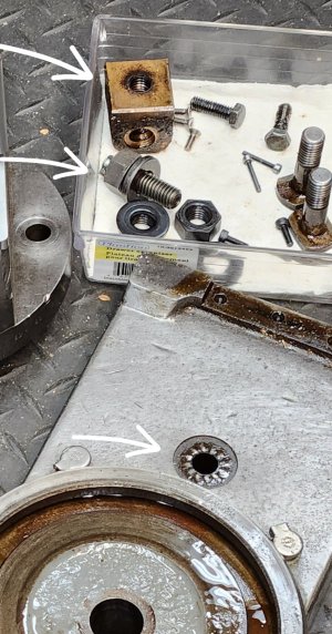
In the next couple weeks/months, I'm going to tackle making a new cross-slide lead-screw and nut. Not that there is anything terribly wrong with the existing units, I just want to do it for the experience, and hopefully get less than the 0.020" backlash it currently has.

The lathe is a Standard Modern 1654 Utilathe. The cross-slide lead-screw is LH3/4"-5tpi Acme. My goal is to machine a tighter tolerance 4C (ceneralized) Acme thread for both the lead screw and the nut. The leadscrew shouldn't be an issue; the nut a little more difficult, but the most difficult part might be in the alignment of the two parts so that they won't bind. Maybe some sort of a floating or adjustable mount for the nut?

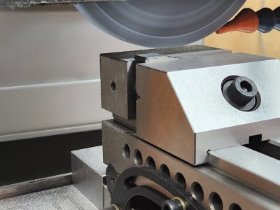
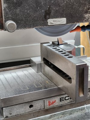
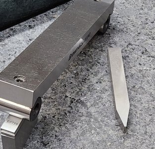
We'll address that hurdle when we get to it. In the meantime, I just ground a 3/8" HSS tool bit for the Acme form. I made the nose smaller than 5tpi, so that I can fine tune the thread.
 

Attachments

  • 20240218_142907.jpg
    20240218_142907.jpg
    328.8 KB · Views: 29
  • 20240218_150330.jpg
    20240218_150330.jpg
    760.6 KB · Views: 29
  • 20240218_151907.jpg
    20240218_151907.jpg
    603 KB · Views: 29

Darren

Ultra Member
Premium Member
Did you grind in some side clearance? I don't have a sine vise, so i use a small grinding vise clamped in my larger grinding vise to set the compound angle with angle blocks to set the angles.
 

thestelster

Ultra Member
Premium Member
Did you grind in some side clearance? I don't have a sine vise, so i use a small grinding vise clamped in my larger grinding vise to set the compound angle with angle blocks to set the angles.
I had to make a 14.5° angle block out of 1/4"CRS plate. This was used to set up the angle for the cutter which was clamped in the sine vise, and then tilted 2.5° for flank clearance.
 

Darren

Ultra Member
Premium Member
The last crossfeed screw and nut i made, I bought an Acesteel 9/16-8lh acme tap off Amazon and then made the screw to fit. It worked out very well. Ended up with very close to zero play. made the screw out of 1144 stressproof and the nut from a chunk of bearing bronze.
 

PeterT

Ultra Member
Premium Member
Snap a pic of your existing nut when convenient. I want to make a better anti-backlash nut for my 14x40 vs the stock slit & set screw spreader method. But my cross slide table is very space constrained where the nut mounts so many good options just aren't very feasible.
 

Darren

Ultra Member
Premium Member
nut.jpg

Here's what my Emco has. Bolt 14 tightens up the nut. 15 is an oiler. This system works very well and would be simple enough to implement on most lathes.
 

Susquatch

Ultra Member
Administrator
Moderator
Premium Member
Cool @thestelster

I've seen some really nifty split nut designs over the years, ranging from a prybar screw to open up one side like @PeterT describes to fully split on sliding pins and even one with a tiny lead screw to adjust the lead screw nut!

Is your wear mostly on the nut or is the leade screw worn in the middle? A new nut is easier than doing both......
 

thestelster

Ultra Member
Premium Member
Snap a pic of your existing nut when convenient. I want to make a better anti-backlash nut for my 14x40 vs the stock slit & set screw spreader method. But my cross slide table is very space constrained where the nut mounts so many good options just aren't very feasible.
Here is a picture of the nut, and the bolt that attaches it to the cross-slide. I'll take better pictures when I take it apart.
 

Attachments

  • 20240209_151702.jpg
    20240209_151702.jpg
    526 KB · Views: 32

PeterT

Ultra Member
Premium Member
Here's what my Emco has. Bolt 14 tightens up the nut. 15 is an oiler. This system works very well and would be simple enough to implement on most lathes.
I have not seen that before. Adjustment from the top, now that is a lot more convenient than mine. But I'm a bit confused, I guess its its sucking the thread ID together kind of clam shell mode. But is that the same ABL action as pulling a segment of the nut axially (like the split nut style)?

My lathe is a PITA. I have to tweak the adjuster screw entering from rear underside of the cross slide within the casting channel, find the screw with a mirror & flashlight & long screwdriver. Lots of fun. I've found it faster to dismantle the table & get at the screw that way.

I'll try & sketch what I was envisioning
 

Darren

Ultra Member
Premium Member
You have it right @PeterT , not really ideal but it does work. Mine has maintained about 1-2 thou since I have owned it without adjustment, and its very smooth to operate.
 

PeterT

Ultra Member
Premium Member
I haven't thought this through completely so there may be a few too many holes haha. The main nut has no split but there is a separate threaded collar nut (round part). In between them are a stack of spring wave? washers (red). But I'm not really sure about how much force they exert & how many required. Once the collar is screwed up into position, slightly compressing the stack with appropriate ABL tension, the screws just hold the position rotationally. Because the main nut is attached to table, the round nut is basically pushing the leadscrew axially, taking up backlash. It is thinner therefore should preferentially wear, so at that point remove 2 screws, clock over to next hole position (I show 6 but there could be larger array). I thought about regular springs acting along the cap screw vs wave washers which might be more tune-able, but they would probably have to be longer & recessed into the main nut block. My nut block is very skinny about the shaft ID so I doubt there is enough room for the cap screw pins & suitable wave washers.
 

Attachments

  • EDT-18-02-2024 6.13.24 PM.jpg
    EDT-18-02-2024 6.13.24 PM.jpg
    13.7 KB · Views: 2
  • SNAG-18-02-2024 6.24.47 PM.jpg
    SNAG-18-02-2024 6.24.47 PM.jpg
    18.9 KB · Views: 1
  • SNAG-18-02-2024 6.38.58 PM.jpg
    SNAG-18-02-2024 6.38.58 PM.jpg
    16.9 KB · Views: 1

Susquatch

Ultra Member
Administrator
Moderator
Premium Member
I haven't thought this through completely so there may be a few too many holes haha. The main nut has no split but there is a separate threaded collar nut (round part). In between them are a stack of spring wave? washers (red). But I'm not really sure about how much force they exert & how many required. Once the collar is screwed up into position, slightly compressing the stack with appropriate ABL tension, the screws just hold the position rotationally. Because the main nut is attached to table, the round nut is basically pushing the leadscrew axially, taking up backlash. It is thinner therefore should preferentially wear, so at that point remove 2 screws, clock over to next hole position (I show 6 but there could be larger array). I thought about regular springs acting along the cap screw vs wave washers which might be more tune-able, but they would probably have to be longer & recessed into the main nut block. My nut block is very skinny about the shaft ID so I doubt there is enough room for the cap screw pins & suitable wave washers.

Yes Peter, that is one of the many design principles I looked at in the past. I don't really like it though. It's too prone to failure of the thinner nut - especially if adjusted too tightly.

I much prefer the double large nuts on slider pins design. But we don't have that option on machines not designed for it. Or perhaps I should say that I just don't know how to do it.
 

PeterT

Ultra Member
Premium Member
Springs would add more gradual, lighter & predictable force but there just isn't much room.
 

Attachments

  • EDT-18-02-2024 8.37.50 PM.jpg
    EDT-18-02-2024 8.37.50 PM.jpg
    18.3 KB · Views: 1

RobinHood

Ultra Member
Premium Member
I think both halves of the split nut should be the same length (just like on the Colchester, or on a Bridgeport mill, for example) for optimum and equal load bearing capabilities. The thinner ring can be used with some success since most of the cutting forces act mostly in one X-direction only on the nut. The equal, but opposite force, would be seen by the nut if the operator did OD turning on the rear side of the part (or ID turning on the front side of the part). I think the thin ring would wear out prematurely since there are few threads to engage the lead screw.

The problem with spring loaded systems is that the springs can compress under load and then you are back to backlash (at least while the springs compress - it will be eliminated again once the force is reversed on the nut).

Some form of mechanical spreading, setting a fixed split, is thus preferred (wedges, set-screws, etc).
 
Top