This is a frequent issue when reconditioning as the relative position of the bearing holding the cross feed screw is now in a different position than the nut.
sorry for inundating with all the photos...... maybe too many but its easy to tell the story that way
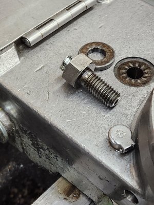
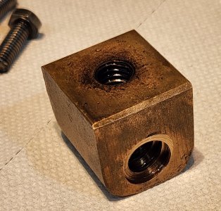
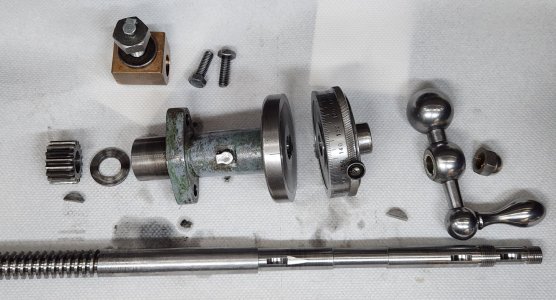
A busted nut (careful, this is a family show) on a DSG compound
View attachment 44518
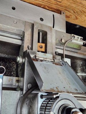
Made a new block
View attachment 44519
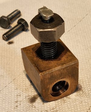
In this case, I machined the existing nut into a cylinder, but it works the same with a new purchased nut
View attachment 44520
Assembled everything
View attachment 44521
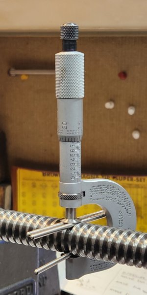
Used a gauge pin to pick up the bore, can't remember why I didn't indicate directly
View attachment 44522
bored the block
View attachment 44523
loctite the nut in (taking care to align oil holes)
View attachment 44524
Done with perfect alignment!
View attachment 44525
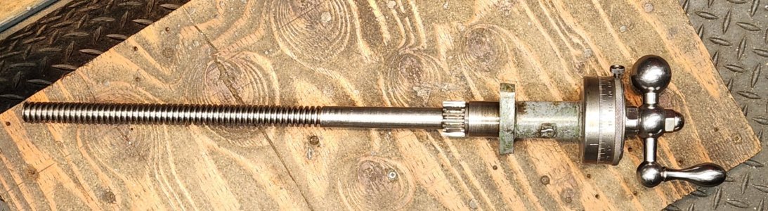
Slight variation on the theme ..... a Maximat (made a new screw for this one as well). First picked up the bore. Threaded section visible, but I indicated more deeply past the thread
View attachment 44526
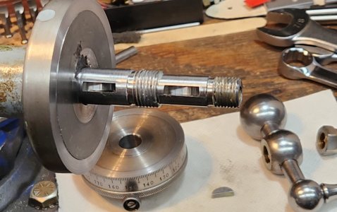
Mount the crossfeed bracket/mount/whatever you call it, bore and sleeve. With boring head and a longer cross slide you can run out of daylight - just mount it so its hanging over the mill's tabl
View attachment 44527
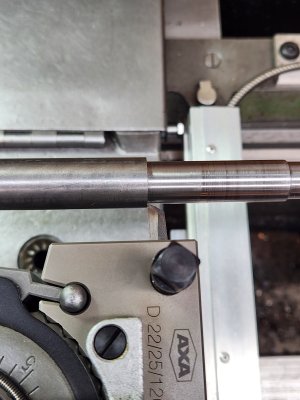
gratuitous shot of screw I made. The ending was done by eye, just carefully and at very slow speed
View attachment 44528
'
Last example.....that I could find (mercy they cried!) Another slide variation in approach. A new Z axis I made for my BCA jig borer. Its a T slot platform with precision spindle I made that replace a head with next to impossible to find collets.
Old nut mounted to the slide. There is nothing to pick up but the ID of the nut, so used a tight fitting gauge pin. Seeming like a good idea, but not accurate enough plus I decided I wanted to put a pair of AC's on the axis.
Used the old mount to transfer mounting pin and bolt locations to a piece of steel
View attachment 44533
Made a new nut holder
View attachment 44534
assembled the Z and indicated in the mounting plate, then drill and reamed the nut holder. I think I turned the nut down or may have bought a new one, same idea though
View attachment 44535
View attachment 44532
View attachment 44531