• Scam Alert. Members are reminded to NOT send money to buy anything. Don't buy things remote and have it shipped - go get it yourself, pay in person, and take your equipment with you. Scammers have burned people on this forum. Urgency, secrecy, excuses, selling for friend, newish members, FUD, are RED FLAGS. A video conference call is not adequate assurance. Face to face interactions are required. Please report suspicions to the forum admins. Stay Safe - anyone can get scammed.

Cross-Slide Leadscrew & Nut

mmcmdl

Machinist/Toolmaker ( retired )
Yes, it does feel good. Of course after spending almost an eternity making it, I've come to the realization that I could never be a real machinist. Or at least not a profitable one!
Oh come on . It's pretty simple to end up with a million bucks . You start with 2 million . :rolleyes: Nice looking work on the leadscrew stelster , been following along . :)
 

Susquatch

Ultra Member
Administrator
Moderator
Premium Member
Yes, it does feel good. Of course after spending almost an eternity making it, I've come to the realization that I could never be a real machinist. Or at least not a profitable one!

Oh bull shit. You are a better machinist than the majority of those money making guys. Most of them just churn out the trinket volume every Tom Dick & Harry wants.

Ya, they make money. But you Sir, make beautiful works of art!
 

thestelster

Ultra Member
Premium Member
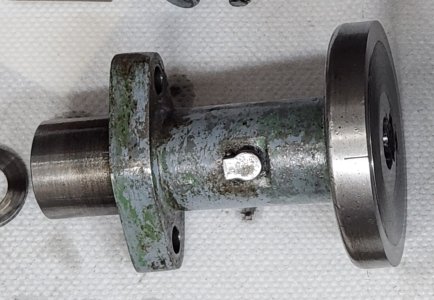
I machined the key seats this morning. Key #505. And assembled all the components and all is good, and fits are good, very good actually!! I'm happy...so far.

Now to start on the nut, as his voice trembles with trepidation!!
 

Attachments

  • 20240311_144351.jpg
    20240311_144351.jpg
    492.4 KB · Views: 8
  • 20240311_151224.jpg
    20240311_151224.jpg
    287.5 KB · Views: 8
  • 20240311_140648.jpg
    20240311_140648.jpg
    645.7 KB · Views: 8

Susquatch

Ultra Member
Administrator
Moderator
Premium Member
Now to start on the nut, as his voice trembles with trepidation!!

I understand completely. I've never done that either. What is the plan? Single point inside threading I assume. Now you need to grind another HSS tool...... Boring bar style?

Talk to us..... I'm sure we can amplify that trepidation of yours to an extreme level......

Insert evil grin here....
 

thestelster

Ultra Member
Premium Member
I understand completely. I've never done that either. What is the plan? Single point inside threading I assume. Now you need to grind another HSS tool...... Boring bar style?

Talk to us..... I'm sure we can amplify that trepidation of yours to an extreme level......

Insert evil grin here....
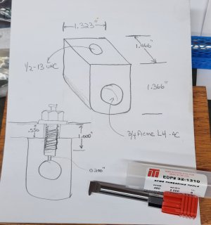
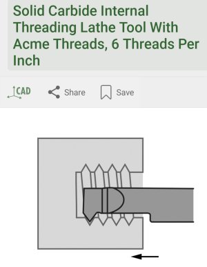
Yes, single point threading. Instead of making a tool, I decided to buy one. Solid carbide, 6tpi, 1/2" shank, and 2" max depth. My nut is only 1.5" long, so should be good.

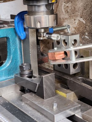
The issue that I'm trying to plan for, is trying to align the crossfeed screw and the nut, because any horizontal, vertical, or angular misalignment will cause the nut and screw to bind. @Mcgyver showed pictures of doing it insitu, and I did that on the compound, but in this instance I'd have to remove the saddle and cross-slide, and I don't have enough room on the mill to do that.
 

Attachments

  • 20240311_163548.jpg
    20240311_163548.jpg
    252.7 KB · Views: 3
  • 20240311_170147.jpg
    20240311_170147.jpg
    588.4 KB · Views: 4
  • 20240311_170136.jpg
    20240311_170136.jpg
    703.9 KB · Views: 3
  • 20240301_094854.jpg
    20240301_094854.jpg
    464.8 KB · Views: 4

Susquatch

Ultra Member
Administrator
Moderator
Premium Member
The issue that I'm trying to plan for, is trying to align the crossfeed screw and the nut, because any horizontal, vertical, or angular misalignment will cause the nut and screw to bind.

Ouch, ya that is a bit nasty, but I'm having a bit of trouble trying to understand the problem.

Axial alignment gets looked after by turning the screw a bit. So it's really only lateral and vertical you need to worry about. I don't think you can do that without a test fit.

Maybe a gob of modelling clay complete with holding screw impressions...... Compress to fit, the clay will take the form, insert pointed screws to mark their location, slowly carefully disassemble? Measure the crap out of it?

Test fit the old nut and if it fits, copy the old nut centering on the dimensions?

Be prepared to make 50 nuts o_O!

I dunno. Never did it either.

Float some ideas and I'm sure the Forum Dog Pack will find something wrong with all of them - but at least that will help you decide.
 

RobinHood

Ultra Member
Premium Member
Vertical location:

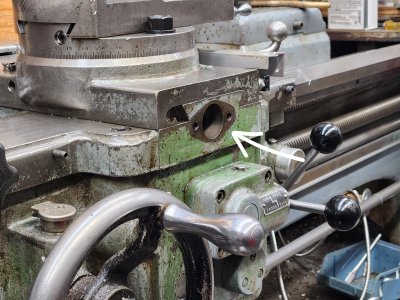
I would make a close fitting “plug” to stick into your carriage bore (green arrow). The plug would be split in half for some distance. Slide your cross slide out towards you so it overhangs a bit. Use adjustable parallels to measure the distance from the center of the bore to the underside of the cross slide (Red arrow). This dimension is the same on the nut - center of the lead screw to the underside of the cross slide.

Lateral location:

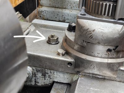
I am almost certain that SM located the retaining bolt in the cross slide inline with the lead screw from factory. You could always confirm that with a measurement: stick a long enough dowel through the same bore. Make a transfer punch and stick it down from the top to mark the dowel. You’ll know right away if you are centred or not.

IMG_2608.jpeg

IMG_2609.jpeg
 

thestelster

Ultra Member
Premium Member
Vertical location:

I would make a close fitting “plug” to stick into your carriage bore (green arrow). The plug would be split in half for some distance. Slide your cross slide out towards you so it overhangs a bit. Use adjustable parallels to measure the distance from the center of the bore to the underside of the cross slide (Red arrow). This dimension is the same on the nut - center of the lead screw to the underside of the cross slide.

Lateral location:

I am almost certain that SM located the retaining bolt in the cross slide inline with the lead screw from factory. You could always confirm that with a measurement: stick a long enough dowel through the same bore. Make a transfer punch and stick it down from the top to mark the dowel. You’ll know right away if you are centred or not.

View attachment 45400

View attachment 45401
Yes, This is what I was thinking too. Except that instead of using a shaft the size of the bore into the saddle to use a shaft the same size (5/8") as the cross-feed screw which goes through the housing which attaches to the saddle.
 

Attachments

  • 20240311_151224.jpg
    20240311_151224.jpg
    211.8 KB · Views: 2

Susquatch

Ultra Member
Administrator
Moderator
Premium Member
Yes, This is what I was thinking too. Except that instead of using a shaft the size of the bore into the saddle to use a shaft the same size (5/8") as the cross-feed screw which goes through the housing which attaches to the saddle.

Geez, I understood what @RobinHood suggested. Sounds to me like this isn't his first rodeo - aka the voice of experience.

But I have no idea what you mean...... What does a half size shaft do for you? Drawing?
 

thestelster

Ultra Member
Premium Member
Geez, I understood what @RobinHood suggested. Sounds to me like this isn't his first rodeo - aka the voice of experience.

But I have no idea what you mean...... What does a half size shaft do for you? Drawing?
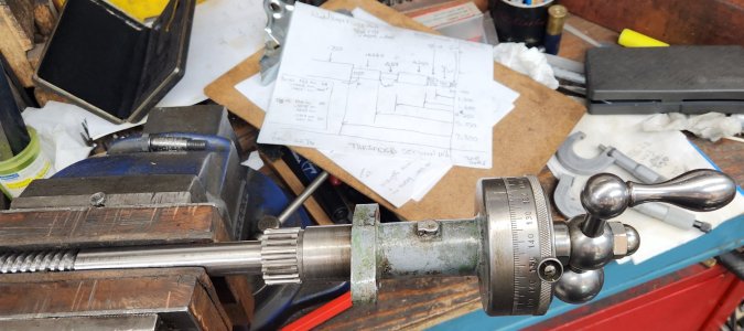
The crossfeed screw section that I made that goes into the dial housing is a very close sliding fit. And that section is about 4" long, so it will have less play. I'm just using the housing as a bushing so that I can run a 5/8" center punch.
 

Attachments

  • 20240301_100751.jpg
    20240301_100751.jpg
    299.6 KB · Views: 1

thestelster

Ultra Member
Premium Member
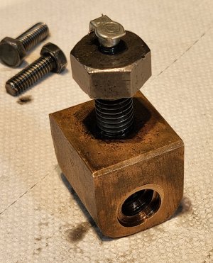
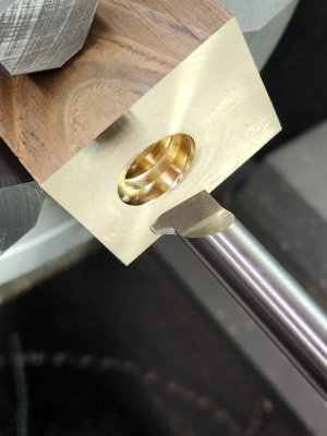
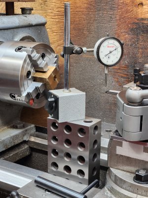
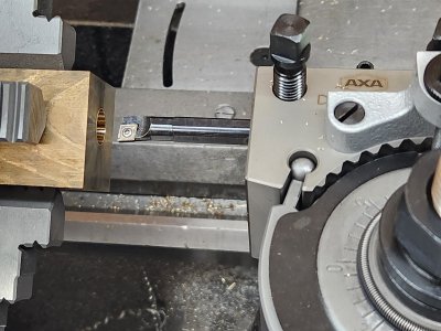
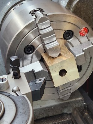
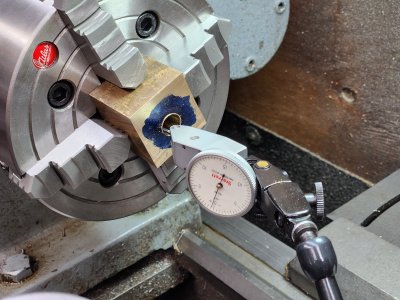
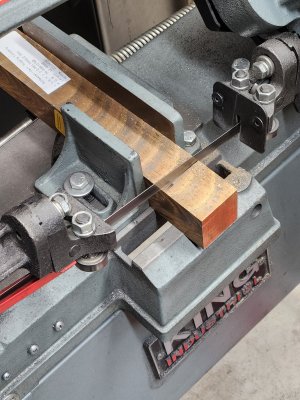
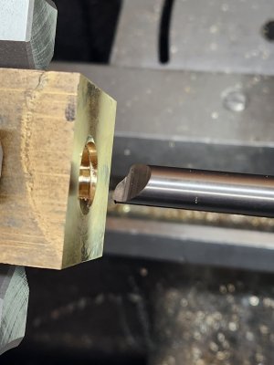
I started on the bronze feedscrew nut.

-cut a section from 12" blank of C95400 aluminium-bronze (I need a new saw blade. It took forever to cut)

-determined position on the blank

-indicated and drilled 1/2" hole

-4-jaw chucked and indicated center

-bored minor diameter to maximum dimension

-threaded down to major diameter, 5tpi

-all looking really good so far

-now to advance the compound in the z-axis to widen the thread groove to get me the proper pitch diameter to fit the crossfeed screw.
 

Attachments

  • 20240312_163423.jpg
    20240312_163423.jpg
    515.2 KB · Views: 12
  • 20240312_181816.jpg
    20240312_181816.jpg
    291.9 KB · Views: 19
  • 20240312_175330.jpg
    20240312_175330.jpg
    342.6 KB · Views: 19
  • 20240312_172248.jpg
    20240312_172248.jpg
    682.4 KB · Views: 13
  • 20240312_172218.jpg
    20240312_172218.jpg
    396.3 KB · Views: 10
  • 20240312_171016.jpg
    20240312_171016.jpg
    398.3 KB · Views: 11
  • 20240312_164027.jpg
    20240312_164027.jpg
    438.4 KB · Views: 10
  • 20240312_122722.jpg
    20240312_122722.jpg
    672.4 KB · Views: 16

thestelster

Ultra Member
Premium Member
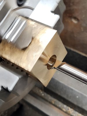
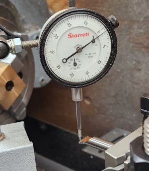
According to the formulas for acme threads, the thickness of the thread at the pitch diameter is: (t)= .5 x 1/p. The 6tpi thread thickness is 0.083", and for 5tpi it is 0.100", therefore I have to move the cutter laterally by the difference, 0.016".

Moved it 0.005", ok.
Moved it 0.004" more......

Fffffffffaaaaaaahhhhhh!!!!!#$%%^$##$%:mad::mad:
 

Attachments

  • 20240312_184454.jpg
    20240312_184454.jpg
    298.8 KB · Views: 9

thestelster

Ultra Member
Premium Member
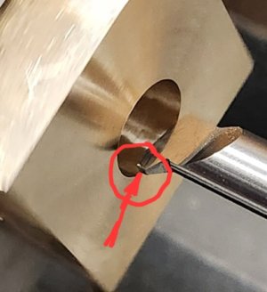
Rubbing?

View attachment 45493

It looks like it might rub, but it's odd that it cut the main groove first and broke on a 4 thou lateral cut.

Perhaps an inclusion in the bar?
It was cutting well. Nice, clean, shavings.

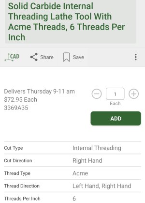
I just checked McMaster-Carr in their description:

I read "Thread Direction: left hand, right hand"

I didn't see, "Thread cut: right hand"

I guess not enough clearance?
 

Attachments

  • Screenshot_20240312_210747_McMaster.jpg
    Screenshot_20240312_210747_McMaster.jpg
    120.4 KB · Views: 5
  • Screenshot_20240312_221018_McMaster.jpg
    Screenshot_20240312_221018_McMaster.jpg
    182.6 KB · Views: 5

PeterT

Ultra Member
Premium Member
Bummer. I wonder if it was grabby bronze syndrome - you had increasing profile contact area & carbide went Schnap. Once upon a time I was drilling bronze parts with a conventional drill in progressive steps just to rough it out for boring. Nothing crazy, moderate rpm & feed, no excess heat. I noticed the bigger drills sounded different in a not good way. Somewhere around 7/8" the drill just locked up in the hole. I cant remember if it turned in the chuck or jerked the arbor loose in MT socket, but it came as a surprise. Brass & bronze likes to be at lower rake angles, at least drilling. But what I cant figure out is my aluminum inserts cut bronze like a dream & they are higher rake angles. They are razor sharp but maybe I'm not pushing them as hard yet.
 

Susquatch

Ultra Member
Administrator
Moderator
Premium Member
I didn't see, "Thread cut: right hand"

Ya, total bummer. The odd thing about that is that the tool cut the full profile which should have been maximum load. Subsequent lateral cuts should be less than half that.

I don't know what to make of that description. What the heck does that even mean? "Left hand Right Hand, but cuts Right Hand". ???? o_O

Frankly, if I'd seen it, it would have sent me into deep research mode and perhaps I'd even have posted about it on here to help me understand it.

You can get another one by tomorrow from MC. But I'd grind a HSS one if I were you. You don't need the profile anymore, just the leading edge. Picking up the thread should be easier to do that way too. Grinding some HSS knowing the hole diameter should also allow you to make the tool stronger than that general purpose carbide one was.

@PeterT's comment above about Grabby Bronze Syndrome is worth thinking about. Again, looking at the failure location might be informative.

Can you use your bore scope to have a really good look at the failure marks?

His comment about sharpness is also relevant. How sharp was that tool? Did you retrieve the tip? Is there enough left to assess the rubbing and relief angles on it?

Hope you had a good night's sleep despite this turn of events by the time you read this.
 
Last edited:

thestelster

Ultra Member
Premium Member
I don't know what to make of that description. What the heck does that even mean? "Left hand Right Hand, but cuts Right Hand". ???? o_O
Maybe, internal threading right hand, external threading left hand. This way the cutter is always moving in the one direction.
 
Top