I think what
@jcdammeyer suggested is pancake!
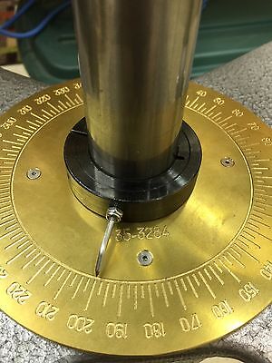
I ordered a few different kinds from Ali to play with. But here is a photo of one of them.
View attachment 35175
In my current thinking the sensor sits flat on top of the compound locating post. The magnet is diametral (N-S is across the diameter not across the cylinder). In my mind, the magnet sits inside the post recess in the compound itself on top of the sensor (like a two layer pancake). They say it can tolerate a 3mm spacing.
IF I can make it work with my Ditron, I will be thrilled. If not, then an Arduino and a display will work with some programming.
I confess that I find it difficult to believe that it can be accurate enough to work really well but they claim 14 bit resolution (16,384 units) which should yield less than 2 minutes of angle assuming everything else is perfect. Which it won't be, but if I just pick a bigger (easier) interval out of my butt, it should easily do tenths of a degree. Plenty good enough for me - IF IT WORKS.