• Scam Alert. Members are reminded to NOT send money to buy anything. Don't buy things remote and have it shipped - go get it yourself, pay in person, and take your equipment with you. Scammers have burned people on this forum. Urgency, secrecy, excuses, selling for friend, newish members, FUD, are RED FLAGS. A video conference call is not adequate assurance. Face to face interactions are required. Please report suspicions to the forum admins. Stay Safe - anyone can get scammed.

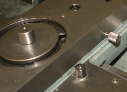
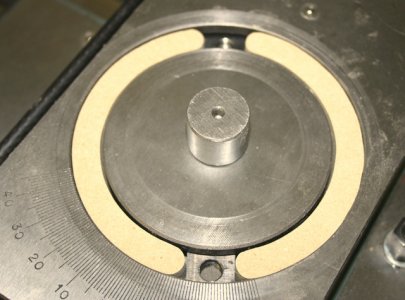
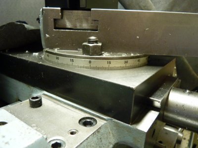
Compound needs a better degree dial

You could print your own, and then modify to fit your needs. This site has a multitude of printable templates and different calculators

I don't want a paper scale, but I am sure there is something there I can use! Maybe even for this project, but for sure elsewhere!

Thank you!
 
This is fascinating John. On sooooo many levels.

It's odd that I never ran across this before. It's really cool.

Do you have a link to the Ali product page instead of a screen shot? I can't find that particular one. I like that it comes with the magnets.

I'm not at all sure that could be added to a compound though. Certainly nothing comes to mind. There is also the problem of precisely centering it. That's easy peasy on a spindle but dunno about a compound.

Must learn more......
https://www.aliexpress.com/item/1005004239312009.html for the AS5600

But there is a better device: The AS5048.
 
I've been waiting for one of you smart guys to find the right electronic gizmo. Ideally, at least on my style of lathe, it should be able to integrate the sensor into the middle area now occupied by cast iron. The T-slot area is off limits & outside of that is running out of room or intersects other important features. The tool post underside could be modified with some kind of sub plate or recessed if it was a simple magnet.

How does one interpret those Ali documents in terms of measurement accuracy? 1-deg? 0,1 deg? Depends on radius? Even if the lathe compound was a more difficult future project, I see value in the gadget for angular indexing without the breaking out the rotary table. Like a chuck rotating on a dedicated plate mounted to mill table. Or upright spin indexer (although the pin system does offer some degree of positioning as is).
 

Attachments

  • J640x465-05852.jpg
    J640x465-05852.jpg
    34 KB · Views: 4
  • J640x475-01481.jpg
    J640x475-01481.jpg
    51.2 KB · Views: 4
It's generally 12 bits of resolution either as an analogue output or PWM. Often supplied as a digital value so you don't need to use an A/D on the uP that interfaces to it. So a simple Arduino could do this.
The best way to figure this all out is to use a rotary table to spin the magnet. Line up the sensor so it's within the measurement distance and then look at positioning accuracy and repeatability.
Just search using keywords like AS5048A and Youtube and arduino...
Well some of this made sense to me John. Words like "The", "and", and "simply" :)
 
The nice thing about the Arduino stuff is you don't actually have to know very much. What I was trying to say is there is lots out there for this particular sensor.
So if you want to double check accuracy you can clone what is posted on one of the web sites and set up the rotary table to check accuracy. If it matches the table well enough then it's likely good for anything and it gets back to a mechanical issue.
ie. Can you mount a small magnet and that sensor on the compound somehow so the magnetic swarf doesn't stick to the magnet and how to get the wires out.
After that a display and ESP32 or Arduino and some help from members on this forum or other groups and bada bing bada boom you have an angular display for your compound.
As usual. The devil is in the details. Mostly mechanical and some wiring. The arduino libraries make the software pretty simple.
 
Sorry for teasing you - this could work very well. I understand that it would normally measure stepper or other shaft rotation. In hindsight, I'm surprised that the feature isn't commercially available for lathe compounds. Not much different than a DRO sensor.
 
Hate to make all this electronics seem irrelevant, but all you need is extra index marks on the compound base. Little scribed plates located every 45* around the circumference, then just a tiny bit of mental math.
 
what about a cam degree wheel? Easy to get and fairly cheap.

Yup, that's actually what first started me looking. But I've never seen one with degree marks on the inside and writing on the outside. I'll have to look harder!

Regardless of how a sensor system might work, I wanna do the wheel. I like things that make sense.
 
Hate to make all this electronics seem irrelevant, but all you need is extra index marks on the compound base. Little scribed plates located every 45* around the circumference, then just a tiny bit of mental math.

As mentioned to @Bandit above. Thats what I have now. Just 60s instead of 45s. Yes, it works. I'd just like a full scale. Always going to have to do some simple rithmetic regardless.
 
My machine has the degree markings on the compound and marks at 45 degrees on the cross slide base.
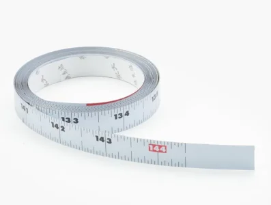
@Susquatch - would this concept work for you. The picture shows the degree tape that is metal and goes 60 degrees either side of zero.
Compound_Degree_Marking.JPG
 
As usual. The devil is in the details. Mostly mechanical and some wiring. The arduino libraries make the software pretty simple.

I agree. I think the primary issue is figuring out how to mount the magnet and sensor on the axis of the compound.

For some reason, i think the AS5048 can be 14 bit. That makes it better than using an indicator - assuming it can be calibrated that finely and assuming other factors don't dilute the resolution.

As usual, it seems like one little project has morphed into three. Originally, all I really wanted was a 360 degree manual scale........
 
My machine has the degree markings on the compound and marks at 45 degrees on the cross slide base.
@Susquatch - would this concept work for you.

Yes, I have been looking at both flat plates that get mounted between the cross-slide and compound or sleeves that slip over the compound. I favour the latter because they can be easily calibrated and inside turned for a light friction fit and perhaps even dog point lock screws.
 
Is this better principle? Its all Geek Greek to me

I skimmed it just for you. But I'd stay away from that one Peter. Unless I missed something, I don't think it will do what he claims. Crap load of work too.
 
Here's my last thought for the day: quick and dirty. Buy adhesive metal measuring tapes from Lee Valley 70539-adhesive-bench-tapes. if you buy the inch/metric scale tape and cut the tape in half lengthwise and then use the mm scale and wrap it around the base of the compound, total error error is about 1.1 degrees over 360 degrees or less because you already have part of the circle covered by your existing scale.
 

Attachments

  • Screenshot 2023-05-27 at 4.04.42 PM.webp
    Screenshot 2023-05-27 at 4.04.42 PM.webp
    20.2 KB · Views: 0
These aren't AliEx priced but they may also give more flexibility in mounting and certainly would have better tech support:

AksIM™ Off-Axis Rotary Absolute Magnetic Encoder Module

The sparkies (said with respect....) gave me one of this family to build into a high end slip ring assembly I worked on in a past life. I'll refer you to the data sheet for the important details but I can somehow imagine feeding the output into a TouchDRO......

D :cool:
 
I played with the AS5600 a bit trying to make a closed loop stepper.
As far as accuracy it matched the microstep positions up to about 1000 steps/rev. After that there seemed to be a lot of differences, some were periodic while others look like noise.
Then I read an article informing me that micro steps are not particularly position accurate, so I don’t know if the differences were caused by the stepper or the AS5600.
Microsteps are not accurate! To run a closed loop stepper system you have to treat the motor as a two phase drive that requires 200 phase transitions for one revolution. That's linked to the feedback mechanism. Doesn't really matter what type of feedback system.

Think of a DC brushed servo motor with a quadrature encoder. In the case of the DC motor you apply a voltage that turns the motor until the encoder position is reached. It's closed loop in that the velocity is ramped up and down as the position is reached. PID and other methods make that all work so it doesn't overshoot or oscillate at the position.

A closed loop stepper isn't that much different other than now you have of course a number of phases to issue and when it reaches the position fine tune that final phase to reach the correct encoder position and not overshoot and not oscillate.

DC Servos have used resolvers and A/D converters to create a binary value to reach. The AS5600 could be used in the same way. The problem with steppers is the torque changes in between full steps.

The LMD18245s I used for the micro-stepping drive on my ELS have a good data sheet that show the current through the windings for each micro-step. The problem is the load and the friction can mean you have sometimes send it 3 or 4 micro-steps before the shaft rotates. Then it 'snaps' to that next stable position. The PID on a closed loop stepper doesn't care about the micro-steps. It just adjusts the two phase waveform until the armature reaches the target position.

If that makes sense...
 
Back
Top