-
Scam Alert. Members are reminded to NOT send money to buy anything. Don't buy things remote and have it shipped - go get it yourself, pay in person, and take your equipment with you. Scammers have burned people on this forum. Urgency, secrecy, excuses, selling for friend, newish members, FUD, are RED FLAGS. A video conference call is not adequate assurance. Face to face interactions are required. Please report suspicions to the forum admins. Stay Safe - anyone can get scammed.
-
Several Regions have held meetups already, but others are being planned or are evaluating the interest. The Calgary Area Meetup is set for Saturday July 12th at 10am. The signup thread is here! Arbutus has also explored interest in a Fraser Valley meetup but it seems members either missed his thread or had other plans. Let him know if you are interested in a meetup later in the year by posting here! Slowpoke is trying to pull together an Ottawa area meetup later this summer. No date has been selected yet, so let him know if you are interested here! We are not aware of any other meetups being planned this year. If you are interested in doing something in your area, let everyone know and make it happen! Meetups are a great way to make new machining friends and get hands on help in your area. Don’t be shy, sign up and come, or plan your own meetup!
You are using an out of date browser. It may not display this or other websites correctly.
You should upgrade or use an alternative browser.
You should upgrade or use an alternative browser.
Compound needs a better degree dial
- Thread starter Susquatch
- Start date
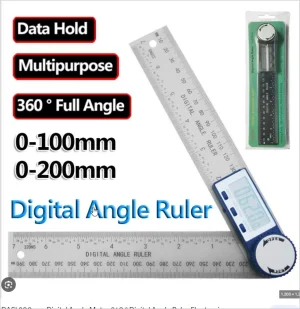
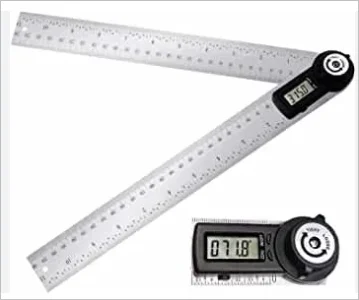
There are all kinds of those digital angle finders, usually hooked up to woodworking tools.
Yes, I have an I-gaging unit and a no-name. They are basically not very good . The rulers are thin and easily misaligned at the pivot and they do not hold calibration
The Lee Valley unit looks more robust and better made even though it is plastic. But it might be worse. Who knows.
Possibly flogging a dead horse, but take a look at the position indicator. Pin, not a scribed line. I suspect this would be much easier to align with whatever degree plate or degree tape you implement.
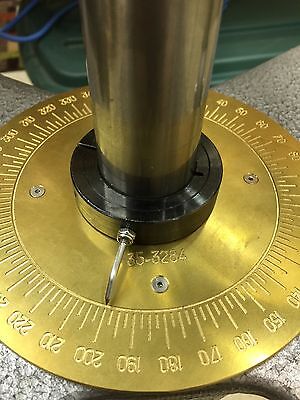

FOR NEW HERMES GTX VISE DEGREE WHEEL ENGRAVER ANGLES OR CIRCLE WORK PRECISION ! | eBay
Find many great new & used options and get the best deals for FOR NEW HERMES GTX VISE DEGREE WHEEL ENGRAVER ANGLES OR CIRCLE WORK PRECISION ! at the best online prices at eBay! Free shipping for many products!
www.ebay.ca
Been busy with spring duties, getting seed in the ground, spraying weeds in the farm fields, and keep my bride happy. But I've made some progress.
I found what is called an R-Axis Table on the web.
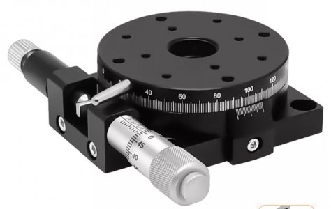
The biggest is 125mm diameter and comes with, the graduations already marked. 125mm gives me 5mm bigger than my compound plinth. That would work fine. It just costs too much. Cheapest I found so far is $84 plus $40 shipping on Ali - YUK! But it is a start.
All I need is the table itself. But it does come with a vernier already setup for the 125mm table marks.
I also got to thinking a bit more about a digital version. The post on my cross-slide for the compound is 0.470 high and 1.25 in diameter. The matching bore in the plinth is 0.625 deep. But there is lots and lots of room to make it deeper. It's hard to see the depth in this photo, but fundamentally there is yet another 1/8 inch on top of the post and that smaller drilled hole provides yet another 0.935 (almost an inch) more depth available that could be machined out as appropriate!
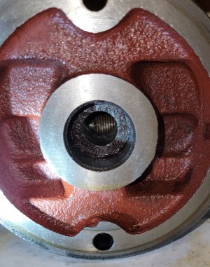
That's the compound leadscrew visible at the bottom of the hole.
I believe one of those rotation sensors and a magnet as discussed earlier could go in there. There are two alternatives - glue the magnet onto the top of the post and the sensor into the compound recess or vice versa. I'm leaning toward magnet in the recess and sensor on the post because that way the wiring could stay in place whenever I remove the compound. But I'm sure practicality will demand other realities when the time comes. I need to get some parts first to get a better idea of how to do this.
Thanks to you guys, a simple improvement project has turned into a much bigger one..... 😵
I found what is called an R-Axis Table on the web.

The biggest is 125mm diameter and comes with, the graduations already marked. 125mm gives me 5mm bigger than my compound plinth. That would work fine. It just costs too much. Cheapest I found so far is $84 plus $40 shipping on Ali - YUK! But it is a start.
All I need is the table itself. But it does come with a vernier already setup for the 125mm table marks.
I also got to thinking a bit more about a digital version. The post on my cross-slide for the compound is 0.470 high and 1.25 in diameter. The matching bore in the plinth is 0.625 deep. But there is lots and lots of room to make it deeper. It's hard to see the depth in this photo, but fundamentally there is yet another 1/8 inch on top of the post and that smaller drilled hole provides yet another 0.935 (almost an inch) more depth available that could be machined out as appropriate!

That's the compound leadscrew visible at the bottom of the hole.
I believe one of those rotation sensors and a magnet as discussed earlier could go in there. There are two alternatives - glue the magnet onto the top of the post and the sensor into the compound recess or vice versa. I'm leaning toward magnet in the recess and sensor on the post because that way the wiring could stay in place whenever I remove the compound. But I'm sure practicality will demand other realities when the time comes. I need to get some parts first to get a better idea of how to do this.
Thanks to you guys, a simple improvement project has turned into a much bigger one..... 😵
Already rethinking the electronic version. The sensor on top means poor oil drainage down from the compound leade screw. But the magnet can be the ring version which has a center hole that could be used for oil drainage. The sensors are sold with both solid and ring version magnets. If the sensor is small enough, it could be mounted on top of the post with screws and include a plastic oil shield. Wires will be a problem but not a huge one.
Last edited:
Just had a flash recollection that my Ditron DRO had a rotary encoder built in. So I checked. Sure enough it's there. Some things are just meant to be!
The manual sucks though so I have no idea how it works. Yet another challenge to figure it out.
Anybody else ever use this function or have any slightest idea how it works?
The manual sucks though so I have no idea how it works. Yet another challenge to figure it out.
Anybody else ever use this function or have any slightest idea how it works?
I've been waiting for one of you smart guys to find the right electronic gizmo. Ideally, at least on my style of lathe, it should be able to integrate the sensor into the middle area now occupied by cast iron. The T-slot area is off limits & outside of that is running out of room or intersects other important features. The tool post underside could be modified with some kind of sub plate or recessed if it was a simple magnet.
How does one interpret those Ali documents in terms of measurement accuracy? 1-deg? 0,1 deg? Depends on radius? Even if the lathe compound was a more difficult future project, I see value in the gadget for angular indexing without the breaking out the rotary table. Like a chuck rotating on a dedicated plate mounted to mill table. Or upright spin indexer (although the pin system does offer some degree of positioning as is).
Sounds like you and I are gunna do this together Peter. I ordered a few sensors and magnets.
What kind of DRO do you have on your lathe? Or are you still TBD like me?
I sent Ditron an Email asking for info on how their DRO works. They list rotary encoder as one of the options for configuring their inputs. I've been holding off ordering a DRO for my lathe until I get the new 3ph motor installed. My plan is to get another Ditron D80 so it works the same way as the D80 on my mill. But I confess that the Touch has me intrigued. I don't know if it supports a rotary encoder though. Course I don't really know that the Ditron will do degrees till I get a sensor and hook it up.
This forum has been a VERY BAD INFLUENCE on me. I've never had so many in-progress projects in my whole life than I've had since I joined here! When I got my Hartford Clone, I had only planned to improve my existing machining activity. It never dawned on me that getting advice from this crowd is like injecting myself with HSS Narcotics.
I have an older gen Newall DRO on the lathe (balls in tube style scales). Its a 3-axis display but I removed the 3rd (compound) some time ago. I'm not sure what flavor of language it reads. I've heard they are 'standard' to many mainstream DRO's but that might be a loaded term with all the offshore alternatives on the market. One thing the compound taught me is the shielded cable running from the tool post area back to the rear of lathe & up to display box can get in the way sometimes. Not a major obstacle but something to be cognizant of. Unfortunately what we want is something like a pancake, most of the encoders are more cylindrical cannister form factor. And that about all I know LOL.
When I have some time I'll try to find my mechanical ideas. The existing crappy scale gets you within a degree so running a dial down a sine plate or its equivalent for final precision is really quite simple & rapid. The PITA part was keeping the gage stack-up in position laying on its side, so that what I was looking to improve on. A better mousetrap.
When I have some time I'll try to find my mechanical ideas. The existing crappy scale gets you within a degree so running a dial down a sine plate or its equivalent for final precision is really quite simple & rapid. The PITA part was keeping the gage stack-up in position laying on its side, so that what I was looking to improve on. A better mousetrap.
Unfortunately what we want is something like a pancake, most of the encoders are more cylindrical cannister form factor. And that about all I know LOL.
I think what @jcdammeyer suggested is pancake!
I ordered a few different kinds from Ali to play with. But here is a photo of one of them.
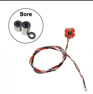
In my current thinking the sensor sits flat on top of the compound locating post. The magnet is diametral (N-S is across the diameter not across the cylinder). In my mind, the magnet sits inside the post recess in the compound itself on top of the sensor (like a two layer pancake). They say it can tolerate a 3mm spacing.
IF I can make it work with my Ditron, I will be thrilled. If not, then an Arduino and a display will work with some programming.
I confess that I find it difficult to believe that it can be accurate enough to work really well but they claim 14 bit resolution (16,384 units) which should yield less than 2 minutes of angle assuming everything else is perfect. Which it won't be, but if I just pick a bigger (easier) interval out of my butt, it should easily do tenths of a degree. Plenty good enough for me - IF IT WORKS.
Looking forward to the resultsI think what @jcdammeyer suggested is pancake!
I ordered a few different kinds from Ali to play with. But here is a photo of one of them.
View attachment 35175
In my current thinking the sensor sits flat on top of the compound locating post. The magnet is diametral (N-S is across the diameter not across the cylinder). In my mind, the magnet sits inside the post recess in the compound itself on top of the sensor (like a two layer pancake). They say it can tolerate a 3mm spacing.
IF I can make it work with my Ditron, I will be thrilled. If not, then an Arduino and a display will work with some programming.
I confess that I find it difficult to believe that it can be accurate enough to work really well but they claim 14 bit resolution (16,384 units) which should yield less than 2 minutes of angle assuming everything else is perfect. Which it won't be, but if I just pick a bigger (easier) interval out of my butt, it should easily do tenths of a degree. Plenty good enough for me - IF IT WORKS.
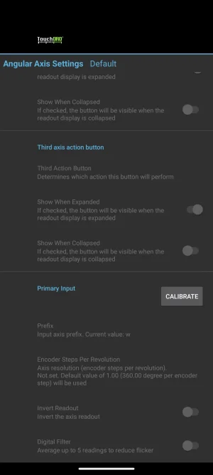
But I confess that the Touch has me intrigued. I don't know if it supports a rotary encoder though.
Cough Using Quadrature Encoders,TouchDRO Manual Page Cough 😉
D 😎
The link won't load Dave. But the question isn't really will it read a Quadrature encoder. The question is "Can a given quadrature input be configured to display the output in degrees 0.0° to 359.9°?"
It might be interesting to put one of those on the dividing head for use on the mill…...
My dividing head will mechanically read in finer increments than 14 bit could provide.
But yes, it might be interesting in the sense that it would be WAAAAY faster than using a divider system and setting the DRO for intervals is easy peasy (assuming it will do that).
This is how I made a bunch of interchangeable parts 12 years ago.
OK, I did that on my new iPad so maybe we don't know each other yet.....The link won't load Dave. But the question isn't really will it read a Quadrature encoder. The question is "Can a given quadrature input be configured to display the output in degrees 0.0° to 359.9°?"
Let's try the link again: TouchDRO Quadrature Encoder Info
A quote from the page:
"Quadrature [incremental] encoders come in all sorts of shapes, sizes and sensor types. The two types most commonly in digital readout systems are linear encoders (such as glass and magnetic DRO scales) and various rotary encoders."
My dividing head will mechanically read in finer increments than 14 bit could provide.
But yes, it might be interesting in the sense that it would be WAAAAY faster than using a divider system and setting the DRO for intervals is easy peasy (assuming it will do that).
OK, you're getting into math that is not my expertise.......
I figured it would be easier to do with the DRO even if it's just: increment -> zero ->increment -> zero etc..
D 😎
Yeah, I have the same ugly deal. But I just realized it's a near-perfect opportunity to add a vernier scale to it - nice straight lines at appropriate, if variable spacing could do 5 divisions of each degree pretty easily. I might try that.View attachment 34940
And it looks better in the picture than real life.
O KOOK, I did that on my new iPad so maybe we don't know each other yet.....
Let's try the link again: TouchDRO Quadrature Encoder Info
A quote from the page:
"Quadrature [incremental] encoders come in all sorts of shapes, sizes and sensor types. The two types most commonly in digital readout systems are linear encoders (such as glass and magnetic DRO scales) and various rotary encoders."
OK, you're getting into math that is not my expertise.......
I figured it would be easier to do with the DRO even if it's just: increment -> zero ->increment -> zero etc..
D 😎
Thanks for the link. Nice read. It describes the electronic interface perfectly.I'm impressed!
What is missing is the description of what the Touch system does with that info once read. That determines what happens to the display readout. We need to be able to read degrees between 0 and 360 then start over. It's not like a linear scale that keeps getting bigger and bigger or smaller and smaller.

