Compound needs a better degree dial

Johnwa

Ultra Member
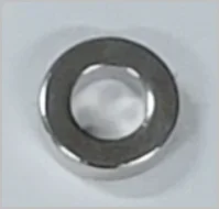
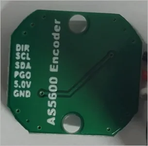
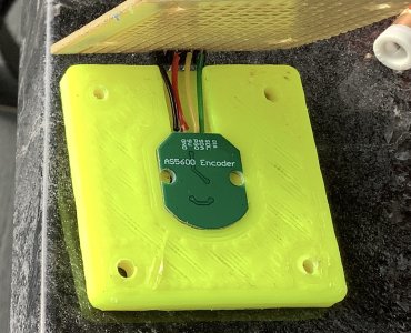
@PeterT The circuit board is stationary. The axis of the magnet is centered on the ic on the board. The magnetic field of the magnet is radial so the N/S poles are on the circumference. As the magnet is rotated the ic detects where the poles are. The board sends that position to an attached processor.
 

Susquatch

Ultra Member
Administrator
Moderator
Premium Member
Can you explain the general layout of these components. For example is the board component stationary datum & ring component rotates with the moving part? Will this talk to Arduino display or some kind of display was included but not shown?

@Johnwa is right but which one stands still and which rotates is really all relative. The chip senses relative rotation between the magnet and itself. So it doesn't matter which one rotates and which stands still. In fact, even the definition of standing still is arbitrary.

This is just a sensor chip on a small circuit board and a magnet. You still need to supply power, collect the data, and output that onto a display. An Arduino could do all of that easily.

However, my goal is to use the Rotary encoding system built into a Ditron DRO or the Touch DRO systems. I'm still undecided but leaning toward Ditron to be compatible with my mill. Either way, I don't want yet another display on my Lathe if I can avoid it.
 

PeterT

Ultra Member
Premium Member
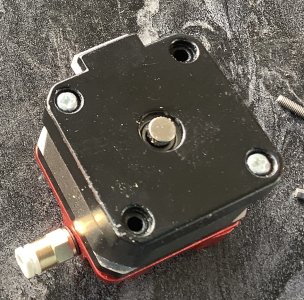
When you say magnet, I assume its this ring? And it overlays the 2 pickup pads on the board maybe?
I'd be interested in this for something even more fundamental. A chuck rotating on a plate/spigot showing me digital angle. Don't even want a rotary table. Just ability to position rotate it by hand to a defined angle & lock it down by whatever means. Don't want to derail the thread, maybe it exists as a project elsewhere. When you mentioned Arduino I though that's where it was going, but I can see the desire to tie into lathe DRO box.

1687580094562.png 1687580143275.png
 

Susquatch

Ultra Member
Administrator
Moderator
Premium Member
When you say magnet, I assume its this ring? And it overlays the 2 pickup pads on the board maybe?

Assuming they exist, said pads are inside the chip itself. There are no sensing pads on the board.

Yes, the magnet is end polarized. I don't believe it needs to be a donut. It could be a pancake. The important thing is that the field rotates as the parts are rotated with respect to each other.

I'd be interested in this for something even more fundamental. A chuck rotating on a plate/spigot showing me digital angle. Don't even want a rotary table. Just ability to position rotate it by hand to a defined angle & lock it down by whatever means.

Sounds entirely possible Peter. Not having done ANYTHING but dream and research just yet, I cannot be considered a good source of advice though.

Don't want to derail the thread, maybe it exists as a project elsewhere. When you mentioned Arduino I though that's where it was going, but I can see the desire to tie into lathe DRO box.

NEVER worry about derailing one of my threads. Derail away my friend. I find such detours increase the overall knowledge I gain and make the journey much more pleasant.

My mention of an Arduino is mostly to understand what can be done but also suggest that an Arduino could act as a translator between the output of the encoder and the input to my DRO. If all else fails, it could also display the compound angle.

That said, this thread is very open ended. I really just want a more accurate compound without needing to indicate it. Any approach that meets that goal is worthy.

Right now I am entertaining 3 alternatives. A Rotary Encoder, adapting an existing degree ring, and making my own degree ring. I may do two of them!
 

PaulL

Technologist at Large
Premium Member
Who makes your HS-800?
Hymseann. One of those fabulous AliExpress deals.
1/4 degree repeatable makes about the best indexing jig in the shop, all I need is a reliable way to lock my spindle. An expanding block in the bore would probably suffice.
 

jcdammeyer

John
Premium Member
I've been following this encoder sensor with interest. Although I'm more interested in multiple revolutions which is why for my power draw bar stepper motor I'm going to mount one of these encoders. They put out the standard quadrature AB + I. More on that later.

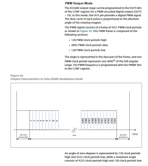
The hall sensor does it differently. It outputs an absolute position as either an analogue signal or as a PWM signal.

The PWM is interesting and looks to be useful for your application. As I understand the data sheet it puts out a fixed frequency and a number of clock periods at one of 4 frequencies. To configure the frequencies and other parameters you need to talk to it via the I2C bus. That can be done with an arduino. If you set the clock to 115 Hz (slowest) it takes 37 seconds to get out the PWM value. Very slow. It's just under 5 seconds at 920 Hz. At that speed, when the output goes high you count 128 periods of the 920 Hz period. Then start measuring the PWM output and counting while it's high. That gives you the (value over 4096) * 360 to get the position in degrees.

1687663431749.png

I'll talk about my quadrature encoders in my power draw bar thread.
 

Johnwa

Ultra Member
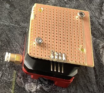
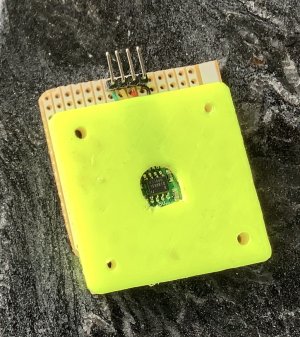
Very nice @Johnwa. How did you align the magnet and sensor? How much does it matter?
The board has a circular outline with a few pieces lopped off. The sensor is in the center of that circle. The outline of the board is centred between the 4 screw holes in the stepper. Fairly easy if you have a 3D printer. I assume that alignment is fairly critical. My setup was to test the accuracy of the sensor using the “known” position of the stepper. It turns out the position of a stepper does not exactly match what you would expect based on the number of steps so my test was inconclusive.
 

jcdammeyer

John
Premium Member
The board has a circular outline with a few pieces lopped off. The sensor is in the center of that circle. The outline of the board is centred between the 4 screw holes in the stepper. Fairly easy if you have a 3D printer. I assume that alignment is fairly critical. My setup was to test the accuracy of the sensor using the “known” position of the stepper. It turns out the position of a stepper does not exactly match what you would expect based on the number of steps so my test was inconclusive.
Micro-stepping is inherently inaccurate. Use full steps as in 200 steps per revolution. Half steps are close but might also drift a tad.
 

Susquatch

Ultra Member
Administrator
Moderator
Premium Member
I'll talk about my quadrature encoders in my power draw bar thread.

Feel free to talk about it here too. The input of my Ditron is Quadrature - so is the Touch.

I had actually expected the Rotary Encoders to have Quadrature outputs. But I didn't do enough research. It turns out that they do their internal measurements using a quadrature process. However, I don't think it's possible to access that directly as external outputs. I know they are programmable so I could be wrong. That research is still to be done.

Ironically, I may need to spoof the existing outputs to create a Quadrature signal for the DRO. What a stupid wasteful process that would be but I've seen and done dumber things in my life.

Anyway, this thread is about improving my compound degree positioning. So everything related is fair game.
 

PaulL

Technologist at Large
Premium Member
Ironically, I may need to spoof the existing outpu
Yep. No quadrature output on that thing, and the PWM output is framed in a way that's PITA to hack into quadrature. But it's easy enough to read the i2c and generate quadrature from it. The only question is how fast you need the signal. For setting your compound you can be pretty slow and any old Arduino should be able to keep up.

[Edit:] But rather than do that I'd probably try using this one: https://www.digikey.ca/en/products/detail/ams-osram-usa-inc/AS5134-ZSST/2334772
 
Last edited:

Susquatch

Ultra Member
Administrator
Moderator
Premium Member
But rather than do that I'd probably try using this one:

Nice, but limited to one degree increments. I can do that easily with a mechanical scale (one is in progress). For the digital, I'd prefer 10ths of a degree or better but would probably settle for 1/4 degree.
 

Johnwa

Ultra Member
Nice, but limited to one degree increments. I can do that easily with a mechanical scale (one is in progress). For the digital, I'd prefer 10ths of a degree or better but would probably settle for 1/4 degree.
If 10ths are enough then the simplest would be to replace the existing pointer with a vernier scale.
 

PaulL

Technologist at Large
Premium Member
If 10ths are enough then the simplest would be to replace the existing pointer with a vernier scale.
Ha! I was thinking of this, and just realized I can use my Z axis DRO to lay out the vernier scale. Given the lack of space on the scale on the compound, I think I can only get my vernier to 0.2 degrees, but that's enough to make indicating in a lot easier!
 

Johnwa

Ultra Member
Micro-stepping is inherently inaccurate. Use full steps as in 200 steps per revolution. Half steps are close but might also drift a tad.
Perhaps a bit of background on my AS5600 project. I was attempting to cut a 100 tooth gear using my electronic indexer. If I had a dog I might have kicked it when I ended up with 100.5 teeth. The encoder test was to see if I could use it to warn of lost steps. That’s when I found that the encoder and stepper positions did not precisely agree. As a result I still don’t know how accurate the AS5600 is nor how critical the magnet placing is.
 

PeterT

Ultra Member
Premium Member
That issue seems to come up on some rotary table / indexer type builds I've watched. I always assumed it was a programming issue, or at least where I've read about Arduino interfaces. Division math or number of sig figs or roundouff...my memory is fuzzy. But also seems like some of the encoder sensors were not behaving. Unfortunately I am technically illiterate so mostly been on the sidelines waiting for the 'right' solution. Maybe a reality check is establish 0.00 deg & reference this with an extended arm on a DTI or something mechanical. Rotate & jiggle & go to 360.00 deg. Now what does the DTI say. 100.5/100*360 suggests is 1.8-deg out. Yah, that will make for a bumpy gear LOL. I feel like the solution is almost there, you guys just need to work longer hours, weekends, evenings, whatever it takes haha
 

Susquatch

Ultra Member
Administrator
Moderator
Premium Member
If 10ths are enough then the simplest would be to replace the existing pointer with a vernier scale.

Not really. My existing scale only covers 120 degrees. I want 360 coverage. Yes, I know I Dan get 360 with 120,bit it's a royal PIA.

The 360 scale I am working on will have a vernier.

Right now, I am focussed on two scales. One mechanical with Vernier, and an electronic one to work with my DRO.
 

Susquatch

Ultra Member
Administrator
Moderator
Premium Member
That issue seems to come up on some rotary table / indexer type builds I've watched. I always assumed it was a programming issue, or at least where I've read about Arduino interfaces. Division math or number of sig figs or roundouff...my memory is fuzzy.

You and @Johnwa are both swimming quite well in the issue that turns me off of digital. Only the programmer or designer really knows how rounding and incremental differences are handled. We have to trust them. I generally don't. One can look at a mechanical gauge and physically see where it is. You can do that with digital unless they add another digit. Some of the better digital meters will flat out say that the accuracy is plus or minus a digit.

This doesn't begin to speak to the linearity of the chosen digitization methodology.

Anyway, such is life. I need to get over it.

Another issue that might be at fault for you @Johnwa is the integer posts vs steps thing. Since you are out 1/2 of a tooth, I'd be suspicious of that. The number of steps is always one more than the number of intervals. To make it simple, 3 steps have only 2 intervals. 360 steps have 359. The best example to explain it is to talk about infants. A baby who is 8 months only is not 1 year old yet. We don't count the year until it is complete yet they are still in their first year.

The issue often comes up when we make a set of stairs. If we have 8 steps, we need 9 ballisters for the rail.

A gear is the same way.
 

jcdammeyer

John
Premium Member
I have no idea how accurate these rotating magnet sensors are. But I don't think you can accurately use a stepper motor to determine how accurate they are. A high count quadrature encoder would be the better way to do it. Here's why.

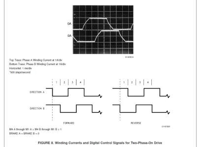
In full step mode the stepper motor has full current through each winding. To step in one or the other direction the current in one of the windings is reversed.

Recall that torque is based on Amperes x Turns. So you get full torque when the windings have the rated current. The problem is that to change the direction of the current you have to oppose the voltage created by the collapsing magnetic field when the current is stopped and then reversed. That's not super difficult. But when the motor is turning it's also a generator creating a voltage and you need the rated motor coil voltage plus that generated voltage to change the direction of the current flow. That's why a 2V motor requires as much as 48V to turn quickly.
1687726503347.png

So why micro-stepping? Because the inherent nature of the motor is that at a certain RPM (Step rate) is develops a harmonic that prevents current flow and motor torque drops to near zero. And the motor locks up.

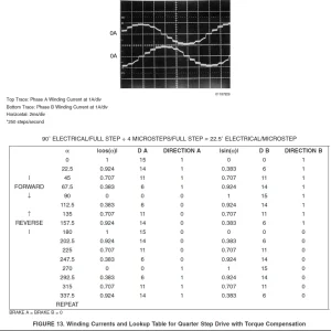
To get around that they don't change the current suddenly but instead in small steps. Micro steps so to speak. The curve below shows how the current in the windings now changes more smoothly. And the table, if you want to analyze it shows that at no time anymore are the windings ever both carrying full winding current. So micro-stepping reduces the torque to 70.7% of full step torque.


1687726397830.png

Now when you look at the table you'll see that for some of the micro-steps the amount of current in one of the windings is 0 or very low. Since Torque is Amperes x Turns we have less torque and the load on the motor may be such that it won't actually turn until the next step when the current in the other winding increases. The above table is for 1/4 step drive. Move up to 10 micro step per step (2000 steps per turn) and it may take 3 micro-steps before the motor moves and then it's a sharp jump to the next physical position. After that it will move relatively evenly but as we approach the next end point it starts to be pulled off again.

So Micro Stepping is great for resonance prevention and lousy for accurate stepping. For that you need closed loop and an encoder.

Hopefully that all makes sense.
 
Top