• Scam Alert. Members are reminded to NOT send money to buy anything. Don't buy things remote and have it shipped - go get it yourself, pay in person, and take your equipment with you. Scammers have burned people on this forum. Urgency, secrecy, excuses, selling for friend, newish members, FUD, are RED FLAGS. A video conference call is not adequate assurance. Face to face interactions are required. Please report suspicions to the forum admins. Stay Safe - anyone can get scammed.

Compound needs a better degree dial

Susquatch said:
O KOOK, I did that on my new iPad so maybe we don't know each other yet.....

Whoa! What did the forum do to my post?!


Susquatch said:
Thanks for the link. Nice read. It describes the electronic interface perfectly.I'm impressed!

There's just soooo much to absorb in all those pages.

Just to add to the info overload, Yuriy has been putting out short videos about TDRO. The Latest gives a short demonstration on how to take advantage of the capability on a lathe. I'm not a video lover but this one is right to the point, no BS and should even pass the @Susquatch filter ;)

D :cool:
 
Last edited:
I'm not a video lover but this one is right to the point, no BS and should even pass the @Susquatch filter ;)

I'm not against videos. I'm against being entertained for an hour to glean 1 minute of useful info.

So, on your recommendation, I'll give it a go.
 
I have the adaware software running and I hover my cursor over the time line and skip past most of the trash. I think on most 30 minute videos I watch maybe 5 minutes? Which is why some of these prolific contributors are really not all that helpful and are only providing lots of content to earn money. not to be helpful
 
You are right. Yuriy passed the Susquatch test. I watched the whole thing. Lots of neat features. Does a good job of covering the content without a lot of useless crap. I'm impressed!
The playback speed option on YouTube helps too. Most videos are easily followed at 1.25 and the slower talkers at 1.5.
 
You are right. Yuriy passed the Susquatch test. I watched the whole thing. Lots of neat features. Does a good job of covering the content without a lot of useless crap. I'm impressed!
Lots of good info in a 9 minute video!

I think your sentiment captures well my impression of what Yuriy has done, not just on the videos but on the product he’s developing including his documentation.

WRT the features, I feel like I’m just scratching the surface of leveraging the utility TouchDRO can give.

D :cool:
 
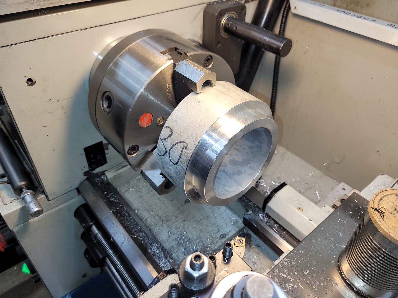
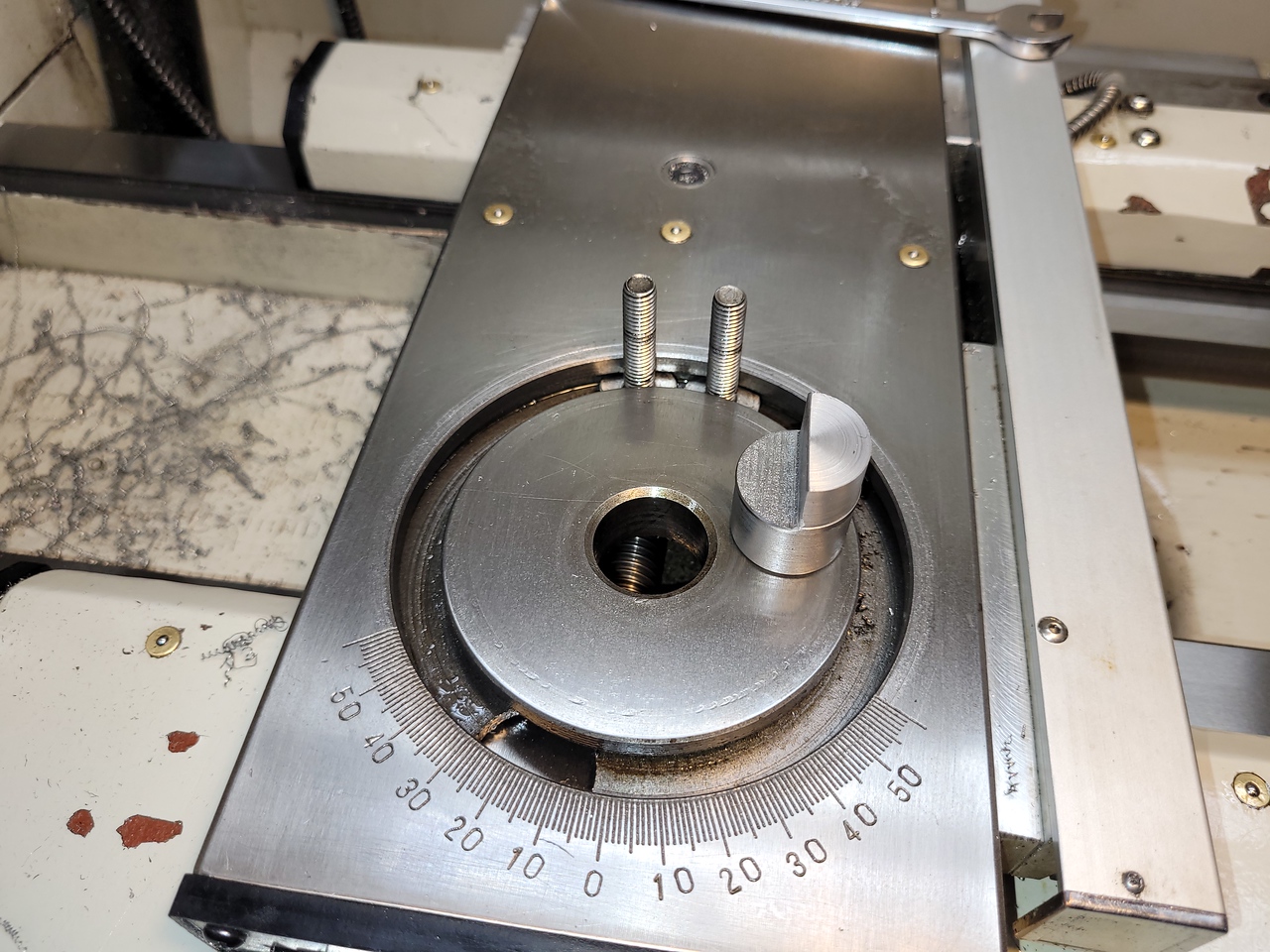
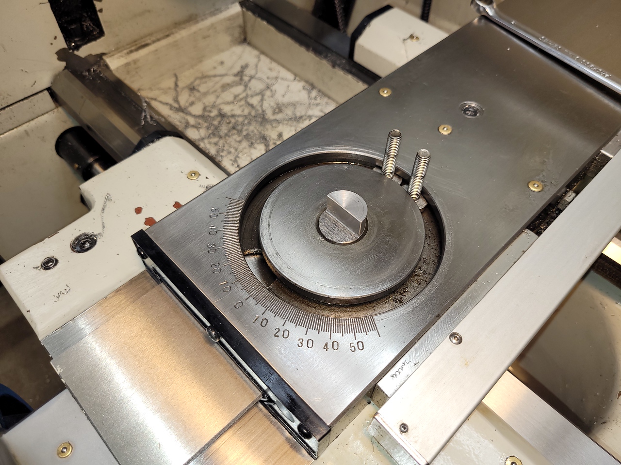
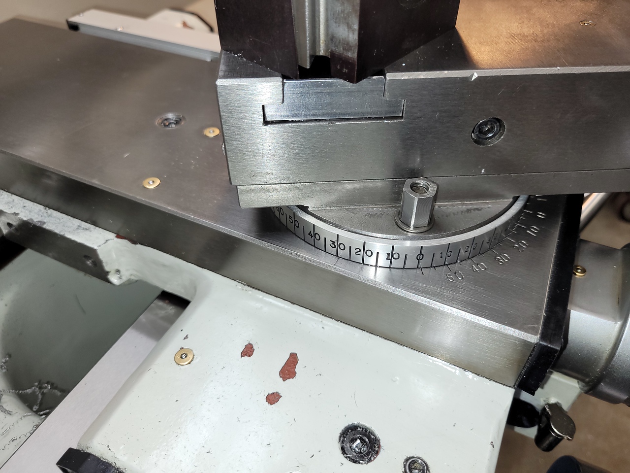
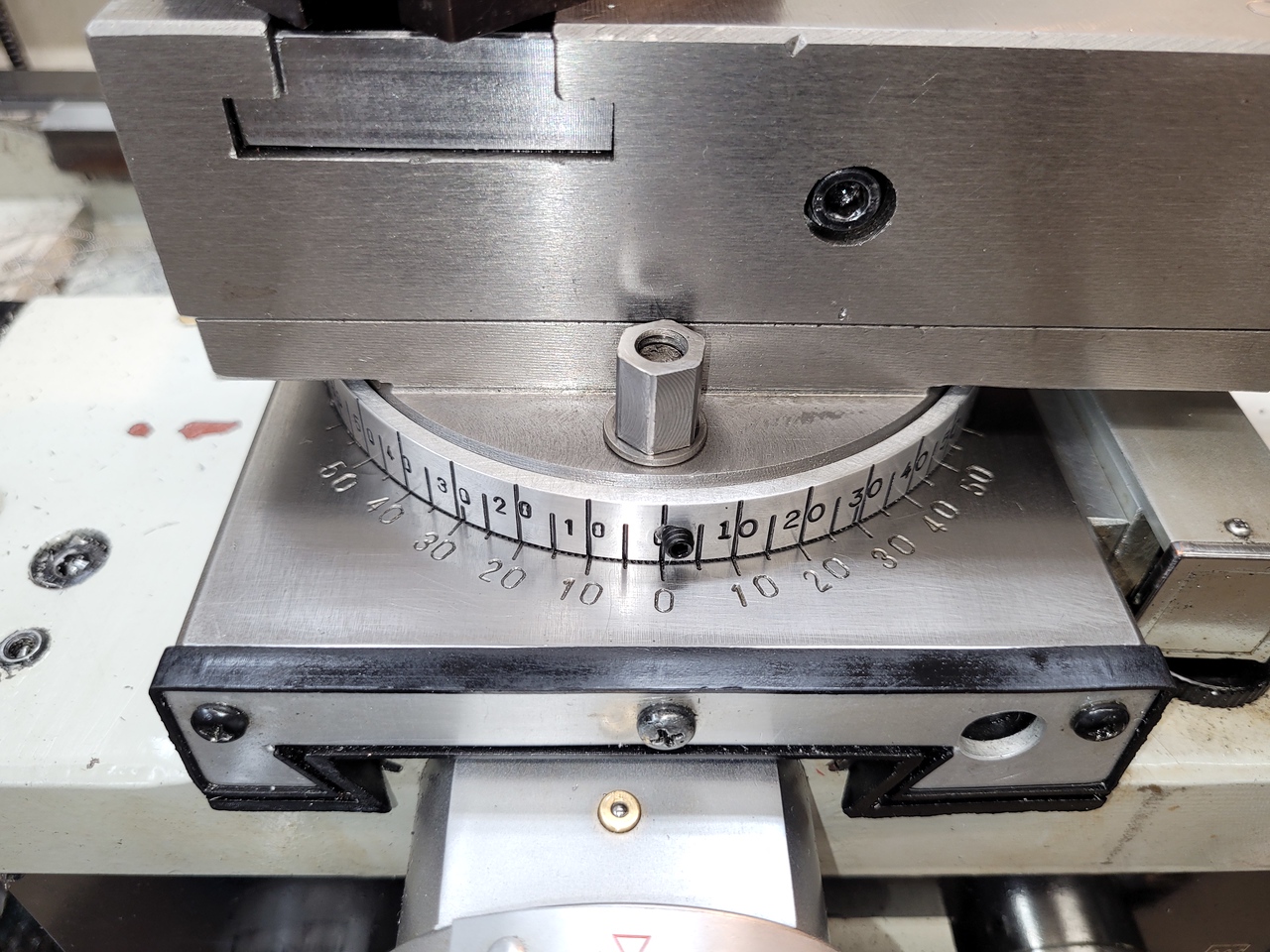
I've been messing with various ideas for a better degree dial for a while now. My plan was to make a sleeve to fit over the round base of my compound and mill grooves in it every 5 degrees and stamp in the numbers, using some 4340 round stock I have. I started on that but found the steel is so hard that my number stamps didn't leave a good impression. I changed the plan to use aluminum and after searching for a suitable piece of material I finally found one under a bench in my buddy's shop. My compound base is 120mm (4.724") in diameter so I machined the OD of the ring to 5" to leave the wall thickness of the ring slightly larger than 1/8".


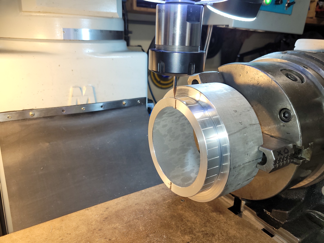
The ring needs to be 1/2" tall and after turning the OD in the lathe I moved it to the mill and used my super spacer to engrave full height grooves every 10 degrees and .312" high grooves on the 5 degree intervals. I used a 1mm ball end mill spinning at 3500 rpm and .020" depth of cut.


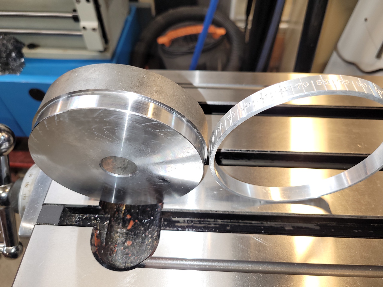
After parting it off in the lathe I made a supporting round from the piece of 4340 to fit inside the ring so I could hand stamp the numbers in my bench vise. This allowed very solid support and after a couple of crooked numbers the rest turned out pretty well.


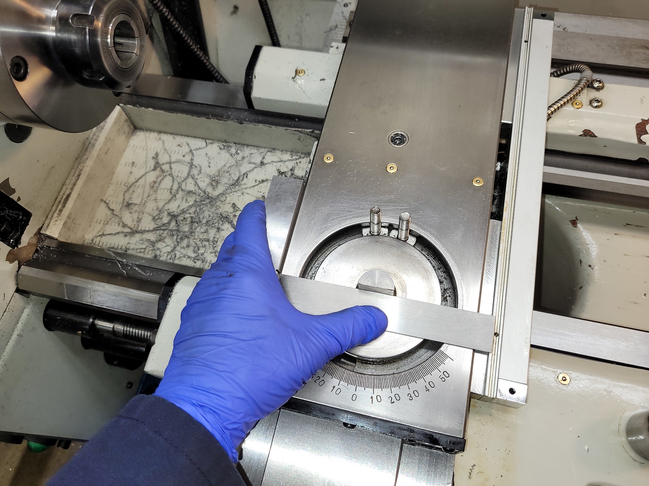
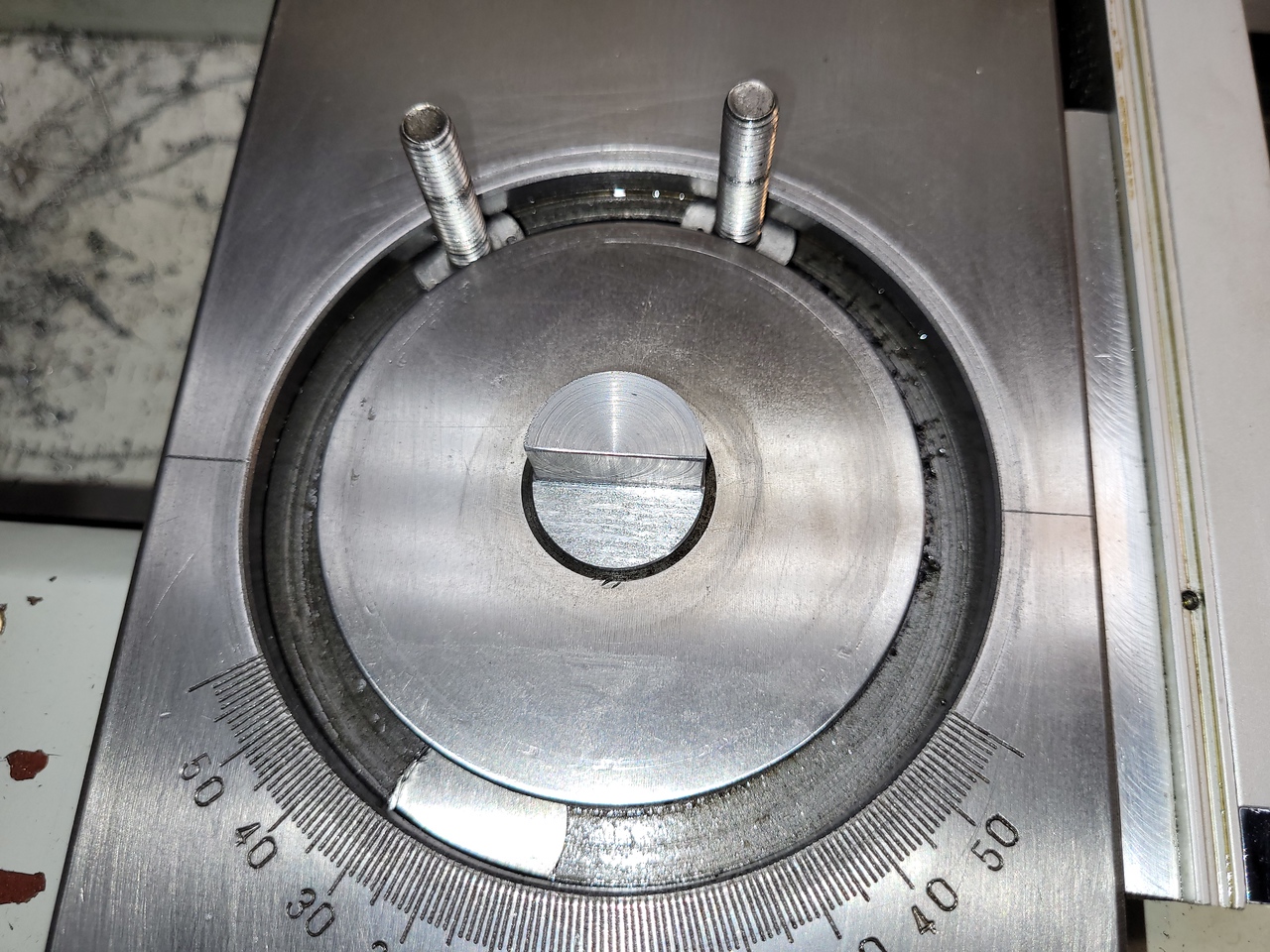
My lathe cross slide didn't have engraved lines on it aligned with the long axis of the machine so I made up a slug to fit the compound swivel on the bottom and machined it exactly in half on the top so I could use a square to manually engrave those lines in.


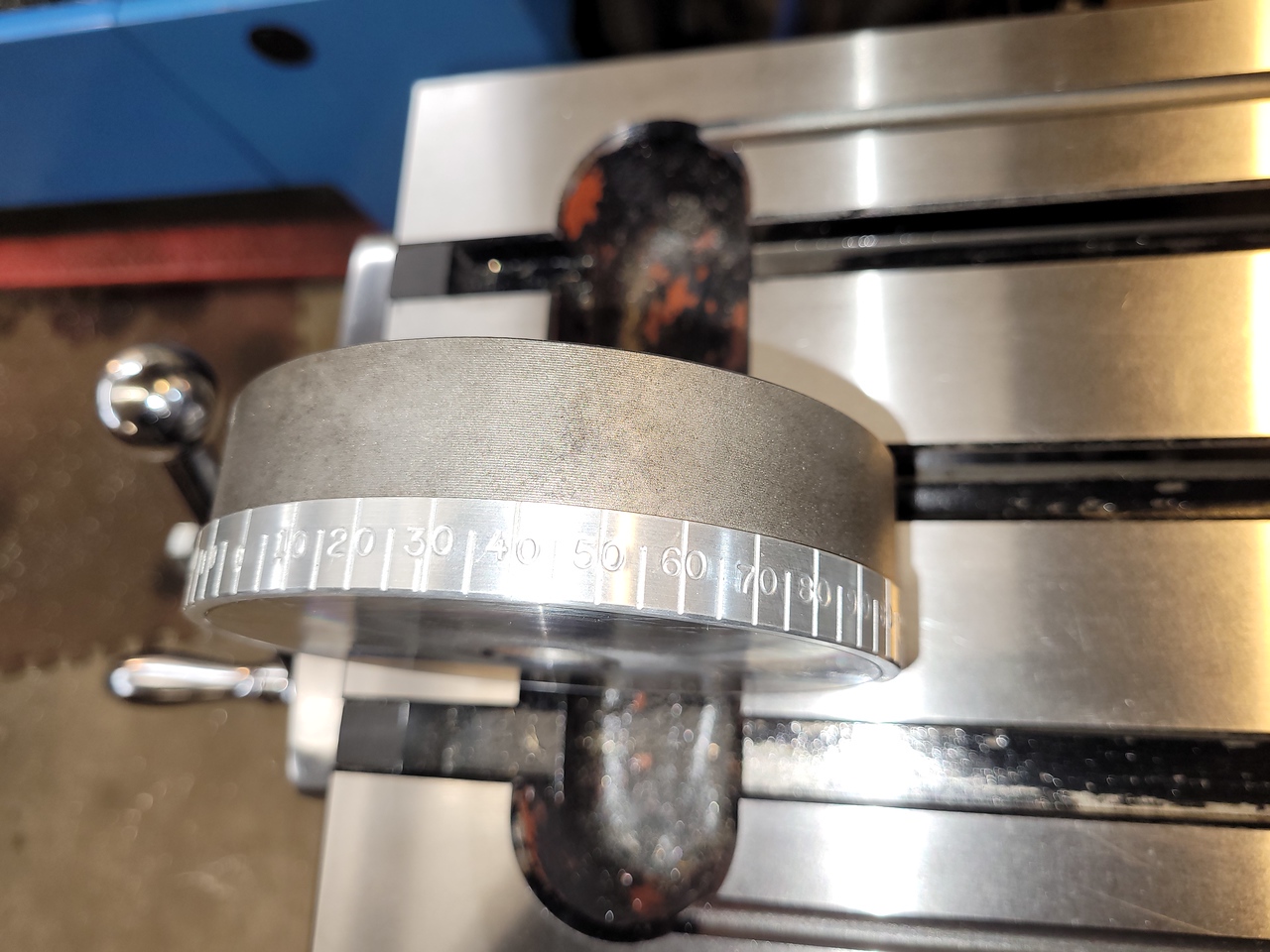
I painted the ring black then, after drying time mounted it back in the lathe and sanded the paint off leaving the numbers filled with black paint. I added one 12-24 set screw to hold it in place, it can easily be realigned if necessary

.


The thickness of the ring makes it hard to see the 1 degree factory marks on the cross slide so I may make a version 2 that is a little thinner.
 
Last edited:
I've been messing with various ideas for a better degree dial for a while now. My plan was to make a sleeve to fit over the round base of my compound and mill grooves in it every 5 degrees and stamp in the numbers, using some 4340 round stock I have.

Absolutely AWESOME John! Exactly what I had in my mind! If I could put 10 hearts on your post I would!

I think I found a pre-etched ring that I will try to do the same thing with. I also have some sensors and magnets on a boat someplace between here and China that I have high hopes for.

We will see.

Kudos to you for making it happen!
 
That looks pretty nice. Never done this myself but I've seen conical 'V' shaped D-bit style cutters used. Some even make the point angle shallower to get a deeper score but still keeping the scribe line thin. The other method is a drag tool using HSS blank, but the mechanisms are not exactly a weekend project.

 
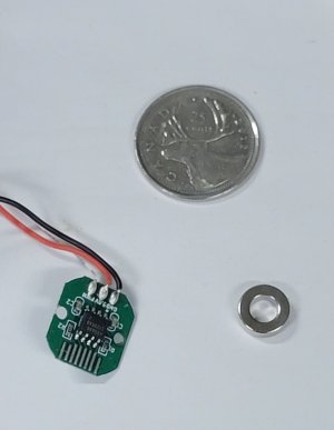
AS5600 Rotary Encoder and Magnets arrived today.

20230623_141802.jpg

Certainly won't be any problems getting it in there..... Biggest problem will be making sure it doesn't fall out! :oops: I've heard some guys complain about that. After looking at this thing I finally understand.

I can't handle little wee tiny stuff like this. Just not used to small anything.

That engraved ring is looking better by the minute!

12 bit resolution.
2^12 = 4096
360 / 4096 = 0.088
or roughly a tenth of a degree.

I have a 14 bit one coming too.
It should yield 2 hundredths of a degree if I'm not happy with tenths.

After looking at the parts, I'm back onto putting the sensor on the plinth and the magnet up inside the compound. Easier to run wires down through the plinth and out the side of the cross-slide. Don't need to worry about twisting them. Might be wrong about that.

Need to figure out how to make the alignment adjustable.

Also, more reading needed. I'm having difficulty understanding how a quadrature signal is generated with only 3 wires.

Much testing and design to follow......
 
I'm currently figuring out how to get the encoder on my lathe spindle to talk to my recently installed HS-800 DRO. I've got 2200 steps per revolution, so only a quarter degree or so. Which is probably plenty for my use.
The challenge is not crossing grounds between the ELS and the DRO. I'm probably overthinking it.
Or maybe I just add in another encoder driven by the DRO.
 
@Susquatch The 3 wire connection is for PWM output. I soldered wires to the little fingers on the other side of the board and used I2C to communicate with the board. IIRC it sends a digital position. I don’t believe it utilizes any Quadrature signals.

I 3d printed a mount for the board and a jig to hold the magnet in position while I glued it in place.
 
@Susquatch The 3 wire connection is for PWM output. I soldered wires to the little fingers on the other side of the board and used I2C to communicate with the board. IIRC it sends a digital position. I don’t believe it utilizes any Quadrature signals.

That isn't what the literature says. But it makes a lot of sense since the connector on the board is actually labelled "PWM".

Could it be that the pulses are already the result of a Quadrature conversion on board the chip?

I 3d printed a mount for the board and a jig to hold the magnet in position while I glued it in place.

No 3D printer here....... Yet!... LOL!

I've been thinking about an adjustable mount so I can put it in place to find the extremes of functionality before gluing it in at the midpoint.

The alternative is some kind of calibrator.

Anyway, my plan is to test it on the bench long before it goes inside my compound.
 
I'm currently figuring out how to get the encoder on my lathe spindle to talk to my recently installed HS-800 DRO. I've got 2200 steps per revolution, so only a quarter degree or so. Which is probably plenty for my use.

Most DROs just count pulses. You tell it how many pulses you have per revolution, it counts and divides for you. 2200 IS A LOT! Who makes your HS-800?

The challenge is not crossing grounds between the ELS and the DRO. I'm probably overthinking it.

If you are really worried about it, isolate the grounds. But the normal method is to tie them all to one common place and make sure there are no hidden ground paths that you don't know about.

Or maybe I just add in another encoder driven by the DRO.

Prolly the easiest (and maybe best) solution if you ask me. That way you can have fewer counts per rev and no circuit worries at all. That is how I plan to do the rpm display on my lathe. The regular DRO rpm reader with prolly 4 or 8 or 10 magnets. Might also do an odd number so I can drill the magnets into the collar from the opposite side and not even need a second collar to capture the magnets. I'll see when I get there.
 
The 3 wire connection is for PWM output. I soldered wires to the little fingers on the other side of the board and used I2C to communicate with the board. IIRC it sends a digital position. I don’t believe it utilizes any Quadrature signals.

I had a closer look at the point you make. The fingers on the opposite side do indeed indicate that's possible.

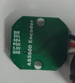
20230623_182152.jpg

These pin indicators are on the bottom side of the board.

Interesting. Might need an Arduino to do this.....

More playing to do now. LOL!
 
or roughly a tenth of a degree. I have a 14 bit one coming too. It should yield 2 hundredths of a degree if I'm not happy with tenths.
After looking at the parts, I'm back onto putting the sensor on the plinth and the magnet up inside the compound. Easier to run wires down through the plinth and out the side of the cross-slide. Don't need to worry about twisting them. Might be wrong about that.
Can you explain the general layout of these components. For example is the board component stationary datum & ring component rotates with the moving part? Will this talk to Arduino display or some kind of display was included but not shown?
 
Back
Top