-
Scam Alert. Members are reminded to NOT send money to buy anything. Don't buy things remote and have it shipped - go get it yourself, pay in person, and take your equipment with you. Scammers have burned people on this forum. Urgency, secrecy, excuses, selling for friend, newish members, FUD, are RED FLAGS. A video conference call is not adequate assurance. Face to face interactions are required. Please report suspicions to the forum admins. Stay Safe - anyone can get scammed.
-
Several Regions have held meetups already, but others are being planned or are evaluating the interest. The Calgary Area Meetup is set for Saturday July 12th at 10am. The signup thread is here! Arbutus has also explored interest in a Fraser Valley meetup but it seems members either missed his thread or had other plans. Let him know if you are interested in a meetup later in the year by posting here! Slowpoke is trying to pull together an Ottawa area meetup later this summer. No date has been selected yet, so let him know if you are interested here! We are not aware of any other meetups being planned this year. If you are interested in doing something in your area, let everyone know and make it happen! Meetups are a great way to make new machining friends and get hands on help in your area. Don’t be shy, sign up and come, or plan your own meetup!
You are using an out of date browser. It may not display this or other websites correctly.
You should upgrade or use an alternative browser.
You should upgrade or use an alternative browser.
CNC plasma cutter build
- Thread starter David
- Start date
That’s coming along nicely, so is there anything you have noticed that you would change in the design so far?
There’s one thing that I might change.
The tabs that are bent over are for some 1/4-20 cap screws which are supposed to apply pressure to the nuts which secure the v-wheels to ensure the v- wheels are snug the the v-rail.
The holes in the tabs are too far outboard to bear on the nuts this so either I bent the tabs in the wrong spot (unlikely as the plans are clear) or the holes are in the wrong place.
Sent from my iPhone using Tapatalk
Last edited:
I wonder if some experts could weigh in here.
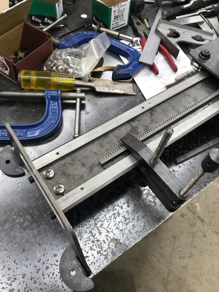
Here's a close-up of the part of the CNC build.
The hole in the tab is supposed to line up over the end of the nut that secures the V-wheel.
I tried as best I could to bend it at the bend line but the hole ended up too far outboard to bear on the nut.
I don't have a bender so I used my 6" vise. I placed the tab in the vise so I could use the larger area for leverage.
I can see that the vertical part arcs over too far.
How could I have bent it so that it was in the correct place?
Thanks John, it was a cold bend, I do have oxy-acetylene so I may go back and see if I can make it a sharper bend.Lots of heat would allow for a sharper bend. Alternatively a weld on tab.
Brent H
Ultra Member
@David_R8 as @Johnwa said I have had good luck with clamping in the vise and heating to a good orange temp and then using a suitable size beater to force the steel to the 90 that I required. You may have success with making some jaws for your vise that have a perfect 90 to get the steel as perfect as possible. Alternatively getting things jigged up and tig welding on the tab may have been a better option.
RobinHood
Ultra Member
You could also use a 90* chamfer mill on the inside of the bend (while the piece is still flat) and machine a V groove almost through the material. Then bend it. Weld it back together on the inside. The bend will be in the exact location you want it. The V can also be cut using an angle grinder with a cut-off disc. This method is more accurate than O-A heating and bending.
I'll see if I can get the vertical bit more vertical with with use of fire. I may end up cutting it off and making a new tab.@David_R8 as @Johnwa said I have had good luck with clamping in the vise and heating to a good orange temp and then using a suitable size beater to force the steel to the 90 that I required. You may have success with making some jaws for your vise that have a perfect 90 to get the steel as perfect as possible. Alternatively getting things jigged up and tig welding on the tab may have been a better option.
@RobinHood thanks for that suggestion. I was wondering if scoring it might help.
+1 RobinHood. Or, start with two pieces and tig-weld strategically.
That's definitely doable!I was thinking the tabs could be cut off and replaced with a 1/2” x 3/4” piece to span the length as a replacement.
@David_R8 Thanks for working out the details.... By the time I get to this, you should have a complete build manual in this thread!
 ")
Since I decided to follow you down this trail, I finally forced myself to put some time into FreeCAD. I can now punch holes in flat material! I figure no use building the CNC plasma cutter if I cannot control it....or rather,draw a picture of a piece of materials with holes in it....
By the time I get to this, you should have a complete build manual in this thread! Since I decided to follow you down this trail, I finally forced myself to put some time into FreeCAD. I can now punch holes in flat material! I figure no use building the CNC plasma cutter if I cannot control it....or rather,draw a picture of a piece of materials with holes in it....
Attachments
@David_R8 Thanks for working out the details....
Since I decided to follow you down this trail, I finally forced myself to put some time into FreeCAD. I can now punch holes in flat material! I figure no use building the CNC plasma cutter if I cannot control it....or rather,draw a picture of a piece of materials with holes in it....
Good work!
I looked at FreeCAD but I’d already invested a bunch of time into Fusion 360.
I’m exploring new machine control software from OpenBuilds.
https://software.openbuilds.com/
Sent from my iPhone using Tapatalk
Last edited:
historicalarms
Ultra Member
another method for accurate bends, should you have a hyd press available. I have used mine (20 T) several times to bend light or heavy (up to 1/2" thick) metal very accurately with judicious placement of sharp edged flat iron to use as bend starters. It seems that if the bend is started in the right place, continuation to finish is easy.
another method for accurate bends, should you have a hyd press available. I have used mine (20 T) several times to bend light or heavy (up to 1/2" thick) metal very accurately with judicious placement of sharp edged flat iron to use as bend starters. It seems that if the bend is started in the right place, continuation to finish is easy.
I have a six-ton bench top press but no dies. Though that’s easy to rectify.
Sent from my iPhone using Tapatalk
Got to spend most of the afternoon in the shop working on the plasma cutter
Though I'm not sure that will be apparent from the photos.
Last update I was laying out the gear rack.
Today I drilled and tapped it, counter sunk the holes for the flat head mounting screws.

I had been fretting over how to maintain the .269" spacing from the V-rail. I measured the height of the gear rack at .25" so I decided to use the cut off pieces as spacers. The stepper motor mounts have provisions to adjust the gear mesh so the .019" difference will be made up that way.
The rack is pretty narrow on its face and I was drill and tapping for 6-32 screws. I could only place holes under the gear peaks other wise there wasn't enough material. Needless to say I had my magnifiers on for this.

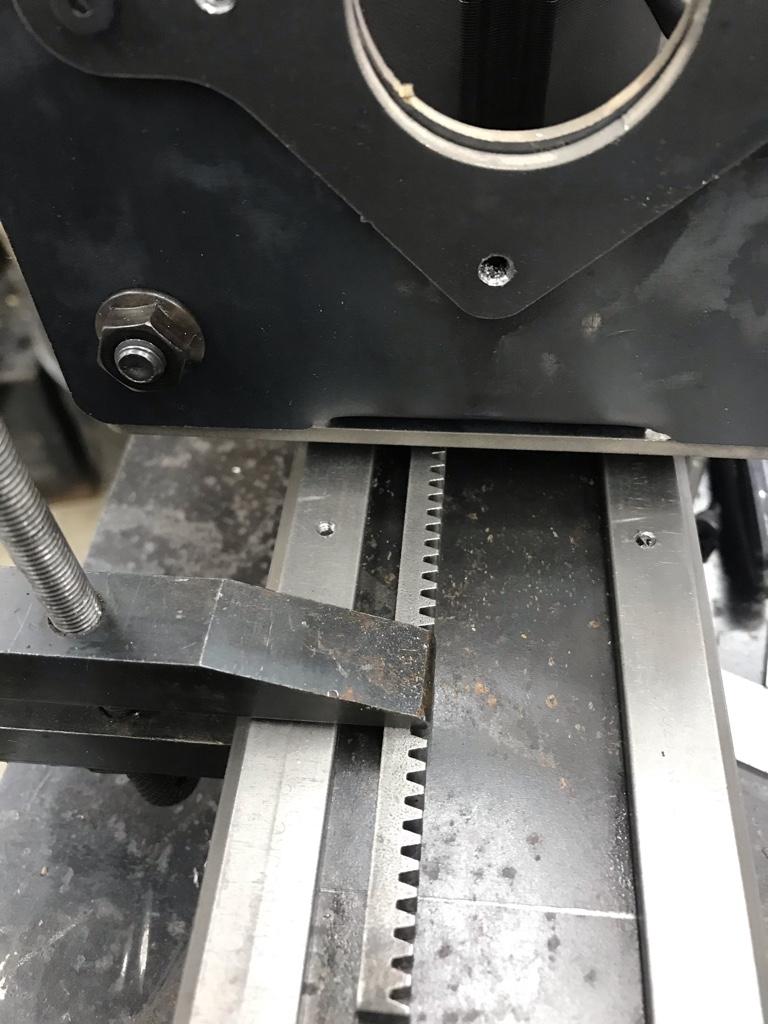
This is the back of the Y-axis. The top and bottom screws are securing the v-rail. the single screw is for the gear rack.

The bill of materials spec'ed pinion gears without set screws so I had to drill and tap the pinion gears for 10-24 set screws. These gears were $16. With set screws they are a whopping $42. Each.

Did a trial fit to make sure everything was copacetic.

Looking down into the Y-axis at the pinion and rack. Definitely a tight fit!

Next steps are to finish the motor mounts; add a roll pin to each for a tensioning spring, build the torch mount (that's a design in progress!) and do the wiring.
It's coming along pretty alright so far. The hairiest part was the gear racks and that's done
Though I'm not sure that will be apparent from the photos.
Last update I was laying out the gear rack.
Today I drilled and tapped it, counter sunk the holes for the flat head mounting screws.
I had been fretting over how to maintain the .269" spacing from the V-rail. I measured the height of the gear rack at .25" so I decided to use the cut off pieces as spacers. The stepper motor mounts have provisions to adjust the gear mesh so the .019" difference will be made up that way.
The rack is pretty narrow on its face and I was drill and tapping for 6-32 screws. I could only place holes under the gear peaks other wise there wasn't enough material. Needless to say I had my magnifiers on for this.
This is the back of the Y-axis. The top and bottom screws are securing the v-rail. the single screw is for the gear rack.
The bill of materials spec'ed pinion gears without set screws so I had to drill and tap the pinion gears for 10-24 set screws. These gears were $16. With set screws they are a whopping $42. Each.
Did a trial fit to make sure everything was copacetic.
Looking down into the Y-axis at the pinion and rack. Definitely a tight fit!
Next steps are to finish the motor mounts; add a roll pin to each for a tensioning spring, build the torch mount (that's a design in progress!) and do the wiring.
It's coming along pretty alright so far. The hairiest part was the gear racks and that's done
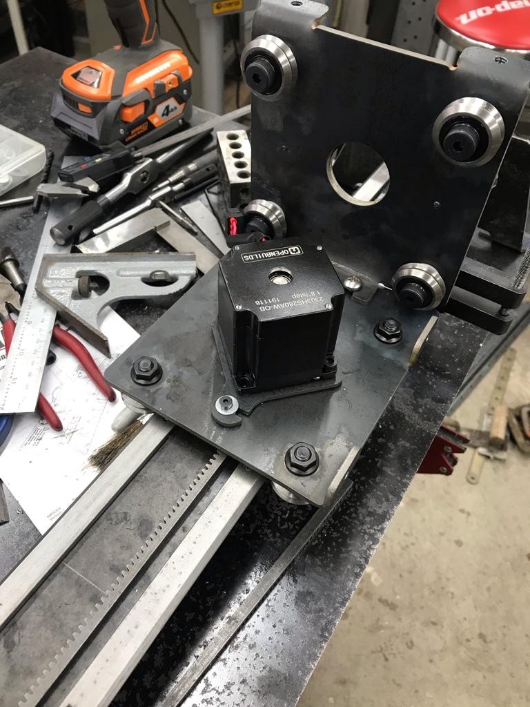
Spent a bunch of time cleaning up the shop to day but did manage a bit of progress on the build.
As @extropic on the Hobby-machinist forum sagely noticed, having the Y-axis gear rack oriented teeth facing up was inviting a build up of crud in the gears.
So I flipped the axis end for end and added a tensioning spring to maintain good gear mesh.
Though looking at the photo I should probably flip the motor mount so the slot faces down.
I also milled .05” off the motor shafts as they were too long and rubbed on the axis plates.
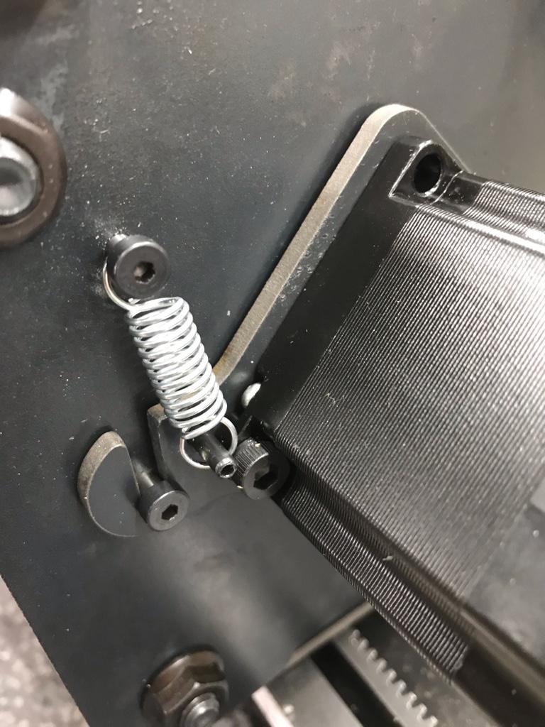
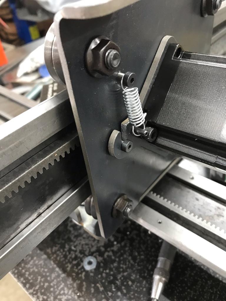
I liked how the tension spring took away the gear lash so I added one to the X-axis too.
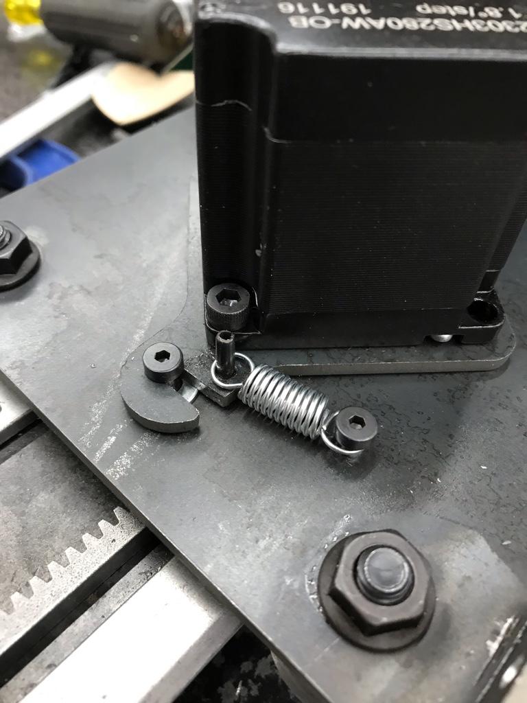
@ShawnR when you build one (see what I did there? ) the holes in the motor mount plates may be too small to accommodate the motors which have a small boss on the mounting face.
I solved this by using my Noga deburring tool to create a small chamfer. A few turns around the opening and the motor fit like a glove.
As @extropic on the Hobby-machinist forum sagely noticed, having the Y-axis gear rack oriented teeth facing up was inviting a build up of crud in the gears.
So I flipped the axis end for end and added a tensioning spring to maintain good gear mesh.
Though looking at the photo I should probably flip the motor mount so the slot faces down.
I also milled .05” off the motor shafts as they were too long and rubbed on the axis plates.
I liked how the tension spring took away the gear lash so I added one to the X-axis too.
@ShawnR when you build one (see what I did there?
) the holes in the motor mount plates may be too small to accommodate the motors which have a small boss on the mounting face.I solved this by using my Noga deburring tool to create a small chamfer. A few turns around the opening and the motor fit like a glove.
Last edited: