• Scam Alert. Members are reminded to NOT send money to buy anything. Don't buy things remote and have it shipped - go get it yourself, pay in person, and take your equipment with you. Scammers have burned people on this forum. Urgency, secrecy, excuses, selling for friend, newish members, FUD, are RED FLAGS. A video conference call is not adequate assurance. Face to face interactions are required. Please report suspicions to the forum admins. Stay Safe - anyone can get scammed.

Other Basic Electronics, Multimeters, & Oscilloscopes

This thread is about basic electrical, electronics, Multimeters, and Oscilloscopes. It is an outcome of interest that various members have expressed about these subjects.

@Janger , @Johnwa , and @kevin.decelles have all recently obtained a starter Oscilloscope so I think the timing is good for a thread like this.

The primary resource will be a book (available on Amazon in paper or kindle) called Electronics for Dummies by Kathleen Shamieh. The book isn't a requirement, but it always helps to have a reference of some kind to facilitate discussion. Other references might get added as the thread progresses.

I'm not picturing this thread as a course, just a good place to ask questions, find answers, and share knowledge and experience about basic electrical knowledge and testing.

As always, a good time and lots of great jokes are expected!
 
The kit came with a wire bnc connector and two alligator clips on the other end. I suppose you could use the alligator clips instead of the probe? No 1x 10x voltage protection though.

Not recommended. The alligator clip cable is for signal generator output. The scope probe comes with smaller versions of clips for various uses. I'd use them with your regular scope probes instead.


After calibration the 120V AC power still looks about the same on the scope. It is connected to a power bar. The power bar is also running the scope, a computer, and the power bar has a power light. I gather these other peripherals could create a difference from an ideal sine wave?

Lots of things can make the power line signal look wonky. Motors, power supplies, inverters, welders, air conditioners, refrigerators, and even things like printers can affect it. Usually it's no big deal. If you want to be certain it's not the scope, use the Scopes built in signal generator to produce a 60Hz sine wave and take a boo at that. I'll bet it's fine.

On the other hand, you also have a tool now that you can use to find out what is affecting your home's electrical system if you want.
 
Just be very careful when measuring AC mains. Often the ground clip of the scope is also connected to the 3rd prong. And the third prong is connected to Neutral back at the breaker panel. So if you accidentally connect the ground clip to the Hot side you get magic smoke. Even if you think the hot side is actually the neutral...
hmm I just tried doing that before you posted John. Glad I didn't blow it up. So the scope does not have a ground wire connected to the power plug. Instead power for the scope is supplied by a two prong USB power adapter 5V 2A it says on the label. The manual does say when using two probes to make sure both grounds are attached to the same ground otherwise the ground is made through the electronics and with potentially catastrophic results. Don't scopes have fuses for protection?

When I measured the ground instead of hot I didn't see an AC sine wave. Instead I saw a bunch of noise on the line with a small voltage 1mv or something.
 
Just be very careful when measuring AC mains. Often the ground clip of the scope is also connected to the 3rd prong. And the third prong is connected to Neutral back at the breaker panel. So if you accidentally connect the ground clip to the Hot side you get magic smoke. Even if you think the hot side is actually the neutral...

The 1014D doesn't have the 3rd plug ground. It's a floating system. Some might call that a disadvantage. But I like it. It's one less thing to worry about.
 
When I measured the ground instead of hot I didn't see an AC sine wave. Instead I saw a bunch of noise on the line with a small voltage 1mv or something.

Hmmm, not sure what you mean. What were you referencing that measurement against. Scope probes are still circuits. They need a complete circuit to measure a signal on. If you only measure the ground with no reference, you are only gunna see RF and noise. Useless stuff. You need a reference. Ideally you can connect the probe ground to ground and then the probe position to each of other two wires to see what they look like. You should see noise on the neutral and the supply voltage (115) on the hot.

BIG WARNING - This advice only applies to Scopes without a grounded plug. Also, pay attention to the maximum voltage limits of the scope and don't exceed them. You can get 100x probes to look at higher voltages like 220 or 550.

P4100 100X Oscilloscope Clip Probe with Accessory Kit High Voltage 2KV 100MHz Bandwidth https://a.co/d/c2LEHw6

Or you can make a little divider circuit.
 
A little off topic. Do any of you electronic guys in Calgary have the equipment to read/write a PIC? The PIC is a 16F73 or a 16F873A. (need to recheck it) I think all I would need is a PICKit 3. Cheap on Aliexpress, but before I purchase I would like to know if the original PIC has the code protect enabled.
 
Last edited:
A little off topic. Do any of you electronic guys in Calgary have the equipment to read/write a PIC? The PIC is a 16F73 or a 16F873A. (need to recheck it) I think all I would need is a PICKit 3. Cheap on Aliexpress, but before I purchase I would like to know if the original PIC has the code protect enabled.
I have an ICD-3 and ICD-4 so if you run out of options you can mail me the chip and I'll check it for you.
 
I have an ICD-3 and ICD-4 so if you run out of options you can mail me the chip and I'll check it for you.
I appreciate the offer John. I'm a little scared to ship this chip. It's the only sample I have and I'm really hoping the code is not locked.

This is more of a winter project and I might as well put an order in for a PICKit from Aliexpress.....should make it here when the snow starts flying. :)
 
I appreciate the offer John. I'm a little scared to ship this chip. It's the only sample I have and I'm really hoping the code is not locked.

This is more of a winter project and I might as well put an order in for a PICKit from Aliexpress.....should make it here when the snow starts flying. :)
And by the time all the shipping is taken into account the cost is probably more than just getting the programmer.

What is the PIC from?
 
And by the time all the shipping is taken into account the cost is probably more than just getting the programmer.

What is the PIC from?
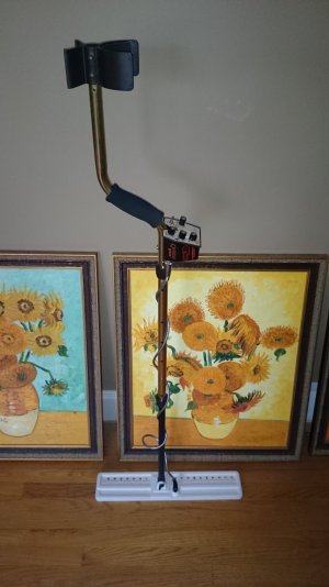
Metal detector. They no longer make it. Golden uMax by Tesoro. Has a very unique ability to discriminate pull tabs but still be able to detect gold rings. Most detectors see gold rings and pull tabs as the same item. Guess which there is more of? :)
 
Metal detector. They no longer make it. Golden uMax by Tesoro. Has a very unique ability to discriminate pull tabs but still be able to detect gold rings. Most detectors see gold rings and pull tabs as the same item. Guess which there is more of? :)
Likely copy protected.
 
Likely copy protected.
Your probably right. I did find the hex code for another model made by Tesoro online that is similar. (It doesn't have the same ability that the Golden uMax has so it is not sought after as much.) There are a lot more of that machine around and it would make me think someone must have read the PIC out on it.. I spent the time and reverse engineered that code to see how that machine worked. To do that I aslo had to find a schematic. Which I did. I basically have the schematic done for the Golden uMax. Just playing on this side.

DSC_3881.JPG
 
Your probably right. I did find the hex code for another model made by Tesoro online that is similar. (It doesn't have the same ability that the Golden uMax has so it is not sought after as much.) There are a lot more of that machine around and it would make me think someone must have read the PIC out on it.. I spent the time and reverse engineered that code to see how that machine worked. To do that I aslo had to find a schematic. Which I did. I basically have the schematic done for the Golden uMax. Just playing on this side.

View attachment 37105
It's very rewarding to be able to reverse engineer and disassemble code and figure out what is happening.
 
I did fin this comment on edaboard

The program picpgm can read the contents of the pic memory to an intel hex file using the savehex option.
There are other tools that will do the same thing.l
 
Just a heads up if you are planning to buy one that Microchip is bad at supporting their older products. Lots of newer ICs won’t be supported by the Pickit and you will need the 4 or now 5 version.

I do have a Pickit 3 and would help but unfortunately I am not local to you. If you do not find anyone here I would recommend trying local makerspaces. I just did a quick search and there seems to be a couple in Calgary. I am sure you could find someone that could help you out there.
 
I did fin this comment on edaboard

The program picpgm can read the contents of the pic memory to an intel hex file using the savehex option.
There are other tools that will do the same thing.l
John, took a little research but I did find some info on your unit. It sounds like it will work. The "enhanced" gives you the ability to use an external voltage (Vpp). Some serial ports did not supply enough power to enable the unit to work correctly while programming.

The first post on this page has a file you can download. (JDM_CD.zip)


direct link to file

www.mcumall.com/JDM_CD.zip

It tells you the correct positions to place various chips in the socket. Has a few different software options and a brief readme file.

I would like to take you up on your offer to try your programmer. I'm in no rush. Thinking maybe around the end of August. I have more then enough summer project to finish up right now. :)


Perry
 
Back
Top