• Scam Alert. Members are reminded to NOT send money to buy anything. Don't buy things remote and have it shipped - go get it yourself, pay in person, and take your equipment with you. Scammers have burned people on this forum. Urgency, secrecy, excuses, selling for friend, newish members, FUD, are RED FLAGS. A video conference call is not adequate assurance. Face to face interactions are required. Please report suspicions to the forum admins. Stay Safe - anyone can get scammed.

Other Basic Electronics, Multimeters, & Oscilloscopes

This thread is about basic electrical, electronics, Multimeters, and Oscilloscopes. It is an outcome of interest that various members have expressed about these subjects.

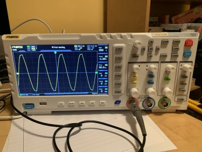
@Janger , @Johnwa , and @kevin.decelles have all recently obtained a starter Oscilloscope so I think the timing is good for a thread like this.

The primary resource will be a book (available on Amazon in paper or kindle) called Electronics for Dummies by Kathleen Shamieh. The book isn't a requirement, but it always helps to have a reference of some kind to facilitate discussion. Other references might get added as the thread progresses.

I'm not picturing this thread as a course, just a good place to ask questions, find answers, and share knowledge and experience about basic electrical knowledge and testing.

As always, a good time and lots of great jokes are expected!
 

Susquatch

Ultra Member
Administrator
Moderator
Premium Member
Here’s a screen shot of data from a pms5003 sensor using the 1013D.

Did you use the "Save Pic" function to get that screenshot?

If I had one of those sensors, SWMBO would want to measure fart particles with it...... So we are not getting one of those!
 

Susquatch

Ultra Member
Administrator
Moderator
Premium Member
Yes and no. The saved pic is a bmp file which the forum didn’t accept. So I took a screen shot on my iPad and uploaded that.

Good on you for finding a way!

Another approach would be to convert it. Many image programs will allow you to "save as" with a different format.

Good to post here so others know how to do it. I've just been taking a photo of the scope.
 

Janger

(John)
Vendor
Premium Member
Scope arrived. Seems pretty good to me so far. I have not checked the calibration. In the picture I'm examining 120V AC from a power bar. The signal is not quite as perfect looking as I expected for AC voltage. Is that just typical for AC power or does it illustrate a calibration issue?
 

Attachments

  • image.jpg
    image.jpg
    364.7 KB · Views: 11

jcdammeyer

John
Premium Member
The power bar or something near it (or for that matter the scope) may have noise filtering hardware. Plug in an electric heater that draws 1kW and look at it again. You may find it will become more symetrical.

Or if you have a step down transformer like 12VAC you can just hand a 12V lamp onto it for a load. Then look at the waveform on the 12V side.
 

whydontu

I Tried, It Broke
Premium Member
Scope arrived. Seems pretty good to me so far. I have not checked the calibration. In the picture I'm examining 120V AC from a power bar. The signal is not quite as perfect looking as I expected for AC voltage. Is that just typical for AC power or does it illustrate a calibration issue?

Have you adjusted the scope probe using the calibration signal and the little screwdriver they provide?
 

Susquatch

Ultra Member
Administrator
Moderator
Premium Member
Is that just typical for AC power or does it illustrate a calibration issue?

I agree with @jcdammeyer . It's unlikely that this is representative. You need a bit of load to check that out as others have suggested.

Have you adjusted the scope probe using the calibration signal and the little screwdriver they provide?

Most Scopes have a calibrate terminal on them to calibrate the probes. This one does not.

Instead, you set the signal generator for a 1KHz square wave, connect one of the scopes 2 inputs to the signal generator output, and then adjust the probe using the provided plastic screwdriver so that the signal is a perfect square wave.

If you want, I'll walk you through the process.

If after adding some load and Calibrating the probes, your signal still looks like that, you have a supply voltage problem that you will have to debug and the scope just paid for itself!
 

jcdammeyer

John
Premium Member
From my Tek scope connected to the unloaded output of a small isolation transformer.
1690306030535.png

Doesn't look much different with a 39K resistor load. I know it's not the scope so either the transformer is the issue or the power line isn't the nicest after all the power bars and PCs plugged into the same circuit.

OTOH, using my Agilent 20MHz Arbitrary Waveform Generator and telling it to make 60Hz 10V it's very pretty.
1690305558029.png
And just to make sure it's not the scope somehow limiting I put two resistors across the output of the transformer. One 33K and one 3.9K and measured across the 3.9K.
1690305916350.png

So this is definitely either the power line or the transformer but not the scope.
 

slow-poke

Ultra Member
From my Tek scope connected to the unloaded output of a small isolation transformer.
View attachment 36827

Doesn't look much different with a 39K resistor load. I know it's not the scope so either the transformer is the issue or the power line isn't the nicest after all the power bars and PCs plugged into the same circuit.

OTOH, using my Agilent 20MHz Arbitrary Waveform Generator and telling it to make 60Hz 10V it's very pretty.
View attachment 36825
And just to make sure it's not the scope somehow limiting I put two resistors across the output of the transformer. One 33K and one 3.9K and measured across the 3.9K.
View attachment 36826

So this is definitely either the power line or the transformer but not the scope.
If it's a small cheap transformer the core is probably saturating.

1)Try passing the agilent waveform through the transformer. More than likely will pass through with minimal distortion, giving the impression that the original mains waveform is distorted, but it's probably not. The Agilent probably has maximum output of 10Vpp or so.

2) Then using mains to power the transformer insert a series resistor in the primary to reduce the input voltage at the transformer input terminals to say 60V and the secondary will likely look like a nice clean sinewave.
 
Last edited:

jcdammeyer

John
Premium Member
And the frequency response of the transformer is?
Likely 60Hz since it's a small isolation transformer.
I don't have a big one handy to isolate the scope and after toasting my fridge compressor board last winter I'm reluctant to measure powering directly.
Plus, as I said before, there is zn enormous amount of powering filtering going on with PCs etc. I'm amazed it looks as nice as it does.
 

slow-poke

Ultra Member
Likely 60Hz since it's a small isolation transformer.
I don't have a big one handy to isolate the scope and after toasting my fridge compressor board last winter I'm reluctant to measure powering directly.
Plus, as I said before, there is zn enormous amount of powering filtering going on with PCs etc. I'm amazed it looks as nice as it does.
The mains waveform is in all likelihood a lot cleaner than shown on the scope. My guess is the transformer used for your test is creating most of the distortion. If inclined try the two suggestions in my post above, that will be revealing. No high voltage or live mains to the scope required.

Back to the original question, if probing mains directly, most likely probe compensation as whydontu suggested. If the probe is compensated, then non linear loads near you.
 
Last edited:

Susquatch

Ultra Member
Administrator
Moderator
Premium Member
Is that just typical for AC power or does it illustrate a calibration issue?

Hey Janger. Here is a step by step procedure for calibrating (setting the compensation) on the 1014D Oscilloscope.

Connect the probes as in the photo below. The alligator clip lead is connected to the green "Gen" output, and the test probe is connected to the orange "CH1". Set the probe to 10x.

20230725_175608.jpg

Generally speaking, it's always best to leave your scope probes set to 10x. They work best that way and it reduces the risk of overloading the scope inputs. You don't actually have to connect the two grounds as both the signal generator and scope input already share the same ground internally as @slowpoke has already mentioned. In this case, it won't matter if you do or you don't. The 1014D is nice in that regard because it doesn't have a mains ground.

20230725_175547.jpg

Then turn on the scope.

Next press the blue "GEN" button to the left of the CH1 input connector. (bottom left corner of the following photo) You will get a popup box that looks something like this:

20230725_180352.jpg

The green type box should be highlighted. If it isn't, then press "OK" in the center of the control panel above the channel boxes.

Here is a photo of the OK button location.

20230725_180726.jpg

Each time you press ok, the green active box will cycle through the options. Press ok till the type box is green.

Now press the up down or left right buttons until the box under the type says square.

The box to the left should say 50%. If it doesn't, just press ok till the duty box is highlighted and then press up or down (but not left or right) until the box says 50%.

Now Press ok again until the "Freq" box is highlighted Green. Now you can press the right or left arrows until the digit you want to change is underlined. Then press Up or Down buttons to change the digits. You want to set the frequency on the 1014D to 1000 Hz like this:

20230725_184847.jpg

That is it for the function generator. Just press the blue "GEN" button to close the generator menu. It should be busy making a 1KHz square wave signal on the alligator clip leads.

Next, you can be lazy and just press the light blue "AUTO" button at the top right. This will automatically set the time and amplitude settings for channel one. It should look something like this:

20230725_182400.jpg

I deliberately offset mine to show a distorted waveform.

Now you get the small plastic flat blade screwdriver that came with your probes, insert it into the compensation port at the connector of your probe as shown in this photo.

20230725_182514.jpg

Gently turn the adjustment one way or the other until the display shows nice square waves like this.

20230725_182535.jpg

That's about it.

Higher end Scopes usually have a special Calibration loop right on the front panel for convenience. Not to worry, this Calibration method works just fine. You can also reset the compensation at higher frequencies if you wish, but 1KHz is common.
 

jcdammeyer

John
Premium Member
Turns out I did have an isolation transformer. It was sitting on the far corner of the table saw extension table with the #42 on it. Along with the terminal blocks, Bridge Rectifier, Fuse etc for creating a 165VDC supply for my 4th Axis Harmonic Drive. Now that I'm using the AC Servos I don't need the massively large 105VDC drive for the 3 DC Servos and Harmonic Drive but I kept it in the cabinet because it's running the harmonic drive (Casting mount for that is project #42).

Anyway, I wired it up as 115VAC in/out and plugged the scope into that. Now no worries about frying anything because the scope ground is touching the hot AC. (Like the fridge compressor drive).

This is the AC waveform from the power bar now. Nothing in the way. But there are a number of computers and adapters all plugged into this same AC circuit.

1690336512173.png

So that's what the AC line looks like inside my office. May look different on the pole but I'm not climbing up there.
 

Janger

(John)
Vendor
Premium Member
Hey Janger. Here is a step by step procedure for calibrating (setting the compensation) on the 1014D Oscilloscope.
Well I just calibrated my two probes - Thanks very much John for the tutorial. It was very easy to follow. Both of the probes needed calibration
 
Last edited:

Janger

(John)
Vendor
Premium Member
After calibration the 120V AC power still looks about the same on the scope. It is connected to a power bar. The power bar is also running the scope, a computer, and the power bar has a power light. I gather these other peripherals could create a difference from an ideal sine wave?
 
Last edited:

Janger

(John)
Vendor
Premium Member
The kit came with a wire bnc connector and two alligator clips on the other end. I suppose you could use the alligator clips instead of the probe? No 1x 10x voltage protection though.
 

jcdammeyer

John
Premium Member
Just be very careful when measuring AC mains. Often the ground clip of the scope is also connected to the 3rd prong. And the third prong is connected to Neutral back at the breaker panel. So if you accidentally connect the ground clip to the Hot side you get magic smoke. Even if you think the hot side is actually the neutral...
 
Top