• Scam Alert. Members are reminded to NOT send money to buy anything. Don't buy things remote and have it shipped - go get it yourself, pay in person, and take your equipment with you. Scammers have burned people on this forum. Urgency, secrecy, excuses, selling for friend, newish members, FUD, are RED FLAGS. A video conference call is not adequate assurance. Face to face interactions are required. Please report suspicions to the forum admins. Stay Safe - anyone can get scammed.

9" SM Utilathe Restoration

Have you surfaced the back side? - AKA the side in your last picture? - then checking it flipped back the other way?

And now the front face shows the 0.002" discrepancy? Going to take another pass on the back face and if the front doesn't get worse proceed to reduce the back to final dimension.
 
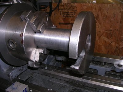
So, I reduced the back of the hub to a depth that catches 4 of the 5 spindle threads and refaced the front.

REGRO.JPG


The front face indicates zero runout and is repeatable. I dismounted the plate 6 times or more and re-checked.

Now the chuck registration indicates 0.001" runout. Is that fallout from squaring the other surfaces up?
 
I think the more threads you have engaged, the more axially aligned the plate becomes to the spindle (a good thing). But threads have a fit tolerance so there will still be potential for slight movement, up-down, in-out & angular. So (in my mind) when the internal flat becomes mated to the spindle nose flat that basically freezes any angular change & provides a consistent stop position. So with this established, you turn the faces & boss & OD... in-situ & that will be about as good as it gets. So if you are achieving 0.001" runout on the registration boss & can consistently measure that repeatably by mount & dismount of adapter plate, then bravo, mission accomplished.

Now if your chuck fits this registration boss nice & snug but shows much higher runout when gripping an accurate OD pin, the culprit is in the jaws/scroll etc. If its like 0.005" you are probably in the range of most medium wear chucks. If its +0.010" well you have to decide yourself if that's good enough. Whatever you grip will turn round of course, but that's not the issue. Its when you re-grip a part which is known to be true & now have lost concentricity for a second turning operation.
 
You are making progress when you are starting to have repeatability.

Its when you re-grip a part which is known to be true & now have lost concentricity for a second turning operation.

And this is where you can make a ”poor man’s adjustachuck”. Turn the register (the one you get a thou runout at the moment) undersized by about 1/2” the max TIR (or just a smidge more). Drill the mounting bolt holes in the plate oversized. Any critical part that needs to be held accurately can now be indicated (by bumping the chuck body on its backing plate while the bolts are just snug) to zero TIR. Job done.
 
You are making progress when you are starting to have repeatability.


And this is where you can make a ”poor man’s adjustachuck”. Turn the register (the one you get a thou runout at the moment) undersized by about 1/2” the max TIR (or just a smidge more). Drill the mounting bolt holes in the plate oversized. Any critical part that needs to be held accurately can now be indicated (by bumping the chuck body on its backing plate while the bolts are just snug) to zero TIR. Job done.

That's probably where I will end up. I was just surprised that the registration surface went out after the facing was done. I'm going to true up the registration and remount the chuck and see where we are at next.
 
You are making progress when you are starting to have repeatability.

And this is where you can make a ”poor man’s adjustachuck”. Turn the register (the one you get a thou runout at the moment) undersized by about 1/2” the max TIR (or just a smidge more). Drill the mounting bolt holes in the plate oversized. Any critical part that needs to be held accurately can now be indicated (by bumping the chuck body on its backing plate while the bolts are just snug) to zero TIR. Job done.
So I turned the registration down 0.005" (0.01" total) and drilled the bolt holes one drill size (1/64") bigger. With a 1/2" end mill shank chucked I bumped the chuck in and got it to 0.001" indicated. This arrangement appears to be repeatable as I dismounted/mounted the end mill and the chuck numerous times and still came in at 0.001".

So this is an improvement over my PRAT.
 
There you go! Good job.

Sometimes the best results happen when one discovers a workaround.... Yes, having 3J chucks that are dead nuts accurate are nice, but if you don’t have one such beast, taking something inferior and applying a clever workaround still gets you there...
 
Glad your getting to a pleasing end to this quest Craig, been following for a few days.
I have a theory on threads that may clear up the question as to why you had a repeatable run out on the face of your new plate when oriented correctly to the lathe headstock but you lost that accuracy when you flipped it to re-machine the plate backside.
if I understand correctly, you have a repeatable .0001 run out when correctly mounted but lost that when you flipped to more than .0005. I think it is how the threads are cut in your plate. Both ways you mount the thing on the headstock uses the same surface side on the headstock threads...but on the plate you use opposing thread surfaces and even though threading can be absolutely true and uniform...what if it isn't...both thread surfaces aren't formed with the same tool. If the thread tool that cut the threads in the plate was a smidge off-angled by manufacture, dressing or mounting, the angle of the trailing face, the one you mount to on the flip side will be a different angle than the leading face. That angle difference could very well "cock" your plate enough to add the additional run-out.

Some of the shooters (Dabbler) might find this interesting.
I proved this theory to myself during a discussion with the owner of A.T.R over precision re-loading with progressive loading press's compared to his "CNC manufactured precision press's" on the other forum we both attend.
His contention was that precision ammo could only be loaded on one of his or similar press and mine was that unless he used a rifle & dies camber cut from the same reamer and tapered collet tightening dies, his thread cut dies& press and shell holders with the proper play allowances to facilitate brass insertion, no mater if they were CNC cut , wouldn't make any better ammo than my press & dies will. I could have used a TPI indicator with an elaborate set-up for my test but I didn't have to. Besides a hand full of different sizing dies ( I have 35-40 die sets to choose from) and my old threaded press, all I needed was a small flashlight. My aim was to prove that any threaded item can have a run-out from the simple fact they have to have slack to be turned...simple...everybody knows that.
My test consisted of screwing a die into the press until it touched the shell holder and observing the sliver of light between the die mouth & shell holder. most of the die brands were very consistent in having a very slight sliver of light...until I tightened the locking ring then every die I tried had a very significant flat v shaped light showing through the die base...this causes a "tilt run-out" for every brass used in it.
What else I discovered was that I could chase that light V around the base of the die by just loosening the lock ring and turning the die in or out a 1/4 turn and then re-locking. I took this to prove that one tread surface is never the same as the one it mesh's with unless very stringent 'copying" methods are used....not much of that happening in machines made in different factories I think.
Enough rambling for today...Ohh ya I never convinced Rick at ATR that ordinary run-of-the-mill presses will produce as good ammo as his CNC machined pieces....
 
So this seemingly simple project took me the better part of the day......:rolleyes:

6.JPG


It's a mock up of my spindle nose 1-1/2" X 8 TPI

1.JPG


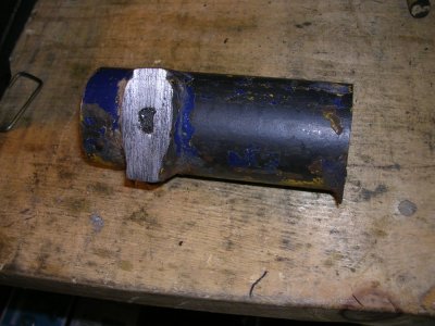
This is the stock I started with. A @Tom Kitta donation (thanks Tom)

3.JPG


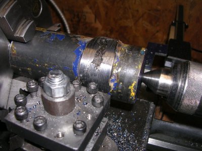
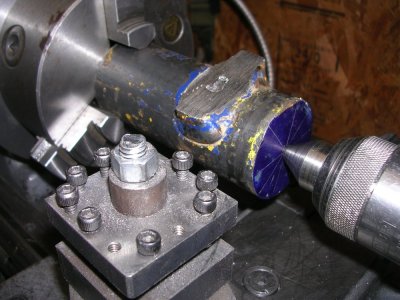
After numerous manipulations using the steady rest, I got the piece to a state where I could attempt to turn off this welded on bracket thingy. I didn't want to waste 2-1/2" of 2" round stock.

4.JPG


It was a bumpy ride turning that wart off, but at lease the weld wasn't as hard as I imagined it would be.

5.JPG


Eventually ended up with this and then it was on to the final product.

7.JPG


And the final result.
 
Last edited:
Way to Go Craig!

So explain this to me please...….

Once I had threaded to target depth, I ended up having to re-thread at target depth 5-6 times before sufficient material was removed for the dog drive plate to thread on? I was surprised at how much material was being removed with those subsequent threading operations.

Craig
 
Last edited:
Boy am I liking this arrangement for drilling on the lathe...….

R20COLLETT.JPG


This is way more stable than a drill chuck....
 
In short, what you dial is not what you cut. a small lathe has a lot of 'springiness' to it. subsequent spring passes bring things clos(er) to the dialed-in dimension.
Question for you @Dabbler : Does the nose radius of a carbide threading tool have the same minimum depth of cut implications as on a turning insert?
I.e. I have CCMT inserts with a nose radius of .4mm or .0158" so that is the number I use for minimum depth of cut with those inserts.
 
Does the nose radius of a carbide threading tool have the same minimum depth of cut implications as on a turning insert?


Welp, as always, it depends... the sharpness of the cutting surface affects the minimum cut depth, thus all diamond honed inserts will have a smaller minimum cut depth.

The radius will affect the surface finish and tool pressure more. The more tool pressure, the more likely (on little hobby lathes) that there will be surface finish issues. When I began doing turning I only used positive rake inserts to minimize pressure. -- They also help with accuracy when you are new to carbide tooling. I finally know how to use both positive and negative rake inserts more or less equally well.

On the triangular inserts I use, I choose the smallest radius I can, but since they are coated, there is at least a 5 thou minimum cut or else things get a little erratic.

For minimum cut depth I use a very sharp HSS tool or vertical shear tool (and the shear tool, not often).

@Alexander will have a lot more info than I do on this - it's part of his daily job...
 
Back
Top