• Scam Alert. Members are reminded to NOT send money to buy anything. Don't buy things remote and have it shipped - go get it yourself, pay in person, and take your equipment with you. Scammers have burned people on this forum. Urgency, secrecy, excuses, selling for friend, newish members, FUD, are RED FLAGS. A video conference call is not adequate assurance. Face to face interactions are required. Please report suspicions to the forum admins. Stay Safe - anyone can get scammed.

9" SM Utilathe Restoration

Hey @YYCHobbyMachinist : can you post a few pictures of the threaded spindle on your lathe and any measurements if there is a collar or gap after the threads? This is purely for making a spindle nose adaptor thing a ma bob :)

Does this make any sense?

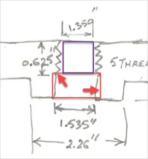
SPINDLEDIMS.JPG


0.20" is the amount of unthreaded 1.5" dia spindle before the 2.059" dia registration boss is encountered.
 
Perfect - so I can make a "mandrel" out of 2" round stock and capture your fitment requirements - excellent
 
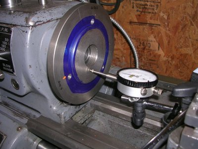
Did some measuring...…..

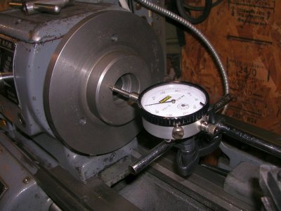
RO1.JPG


The run out on the plate in this location is the same as the registration surface. < 0.001".

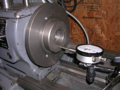
RO2.JPG


When I reverse the plate the run out at the same location is 0.002". In this case the threads bottom out before the plate contacts the registration surface.

Sooo…. I need to push the registration surface out 0.25" or so.

What do you think? Would this work?

https://www.princessauto.com/en/detail/1-1-2-in-shaft-collar/A-p3871423e

Craig
 
Did some measuring...…..

View attachment 11934

The run out on the plate in this location is the same as the registration surface. < 0.001".

View attachment 11935

When I reverse the plate the run out at the same location is 0.002". In this case the threads bottom out before the plate contacts the registration surface.

Sooo…. I need to push the registration surface out 0.25" or so.

What do you think? Would this work?

https://www.princessauto.com/en/detail/1-1-2-in-shaft-collar/A-p3871423e

Craig

I’m confused.
I thought that you wanted more thread engagement...


Sent from my iPhone using Tapatalk
 
I’m confused.
I thought that you wanted more thread engagement...

RO2.JPG


The unthreaded portion of the ID in this image needs to be shorted (almost in half). The surface of the plate hub that normally interfaces with the spindle registration surface needs to be turned down (what the DI is measuring). In it's current configuration it only captures 2.5 of the 5 threads. When the plate is reversed it bottoms out on the threads not the registration surface hence the 0.002" runout, so I can't turn it down without rectifying that situation.

Does that make sense now? Same problem that @YotaBota and @Perry had.
 
Last edited:
I'm not an expert on these threaded spindles but I think job #1 is get the proper plate hub / spindle nose fit first so it will sit where it will always repeatably sit. Then do the machining.
I assumed this is where you were at way up post #447?
 
Again, don't remove metal just because I'm wondering out loud. Others more qualified will chime in. But if you have full thread engagement with it reversed like this & the plate is locked with the hub exposed (your #487 pic) can you not face off the requisite amount from the hub? The hub face will then also be perpendicular to the spindle axis so should mate well. Then do the flip-a-roo re-mount & machine the chuck face, the OD (and unfortunately hope for the best) the chuck registration boss you already turned? Only then will the runout numbers make sense.
 
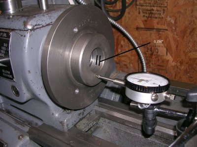
RO2.JPG


this measurement - according to the drawing you posted should only be about 0.250" leaving 0.050" or fifty thou to allow the flange to make full contact with the face of the spindle landing and not bottom out your threads.

That being said -

RO12.JPG


Face 1 here needs to be nice and flat - really slow feed and sharp cutter to get a nice flat face. Flip the adaptor to the other side and then machine down to 0.250 or 0.300 clearance depth with the last pass leaving a baby smooth landing - break the edges and flip the part back over and thread it back on., Then machine the landing (2) as indicated in the picture. The landing 1 should not bottom out in the back of the chuck and the diameter of it should sit in the chuck recess snug.

You only need to get landing 2 nice and flat as that is the surface the chuck is indicated from.

Edited to say: the diameter of the #1 landing needs to be machined after you set up the back so it threads on to the correct depth, there is a lot of meat to play with so if the outer diameter of the 1 surface is not running true you should be able to correct that
 

You have the right idea: you will need a thin spacer to prevent the threads from bottoming out. A large flat washer should probably be sufficiently thick. The washer’s two surfaces will need to be parallel so it does not introduce any further errors. You can check them with a mic. Fix them with sand paper on a surface plate, if required.

then proceed with your plan as you and @PeterT are discussing.
 
I had this same problem when I was making the backing plate for my 4-jaw.
I bored out some of the threads from the register side of the plate so that the register could run up against the face of the spindle. Worked like a charm.
Or maybe I'm misunderstanding the problem.
 
When I made a faceplate for my Southbend I did what I believe @YYCHobbyMachinist is proposing. I made a spacer that fit over the register and butted up against the shoulder of the spindle. When the faceplate was screwed on backwards it butted up against the spacer and hopefully held the front of the faceplate perpendicular to the spindle axis. That way when the rear of the faceplate was bored ot and faced off everything was aligned.
 
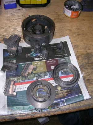
Per @RobinHood 's suggestion, I opened up the chuck...

CHUCKDISS.JPG


And gave it a good cleaning. Everything looks good.

There was grease in the back end (rack and pinion side) which brings up that old debate again.
 
View attachment 11938

this measurement - according to the drawing you posted should only be about 0.250" leaving 0.050" or fifty thou to allow the flange to make full contact with the face of the spindle landing and not bottom out your threads.

Brent,

I've discovered 0.25" isn't sufficient. You may want to use these dimensions instead.

Dims1.webp


Looks to need at least 0.33". I'll confirm this later today once I have another spacer made up.

Craig
 
This is what I was getting at before. I modified/exaggerated your sketch a bit just to illustrate. Are the red surfaces intended to be precision fit to the spindle nose? Or is it just the step surface is critical - must be perpendicular & concentric to the threads & the cylindrical surface has a bit of clearance? Have you been able to find a tolerance spec or something that correlates to that spindle nose?
 

Attachments

  • 2020-11-29_14-35-08.webp
    2020-11-29_14-35-08.webp
    12.3 KB · Views: 5
This is what I was getting at before. I modified/exaggerated your sketch a bit just to illustrate. Are the red surfaces intended to be precision fit to the spindle nose? Or is it just the step surface is critical - must be perpendicular & concentric to the threads & the cylindrical surface has a bit of clearance? Have you been able to find a tolerance spec or something that correlates to that spindle nose?

As far as I can tell those surfaces are of no significance and vary somewhat between my PRAT 3J, PRAT 4J, and drive plate.

This has me puzzled though.

REFACED.JPG


I resurfaced Brent's surface 1 using a sharp HSS tool and the power cross feed (godda love that feature). She is smooth as can be and shows zero runout.

SPACER.JPG


Then I made up this 0.345" wide spacer to extend the spindle registration surface. It measures very consistently all the way around.

REVERSED.JPG


But when I reverse the plate I still get 0.002" runout both with and without the spacer installed?

So not sure what is going on here.
 
Have you surfaced the back side? - AKA the side in your last picture? - then checking it flipped back the other way?
 
Back
Top