• Scam Alert. Members are reminded to NOT send money to buy anything. Don't buy things remote and have it shipped - go get it yourself, pay in person, and take your equipment with you. Scammers have burned people on this forum. Urgency, secrecy, excuses, selling for friend, newish members, FUD, are RED FLAGS. A video conference call is not adequate assurance. Face to face interactions are required. Please report suspicions to the forum admins. Stay Safe - anyone can get scammed.

Tool Post Grinder

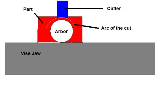
Here's a trick. locate or make an arbor that is the same diameter as your hole (or close, it doesn't have to be perfect)

Clamp the workpiece in the vice with the arbor resting on top of the jaws. You can take successive cuts, making a concentric arc made of short lines that way - the result if very nice, and no thought or extra work to follow the inside circle...

Sorry @Dabbler , it isn't obvious to me what you mean. I did think about using a small fly cutter with a longer than normal tool stick out. Is that sort of the idea?

I know the job is done, but if there is something to learn, I want to learn it.
 
This might not help much, but cuts are made across the part along the Y axis, and the part is indexed (or rotated, if you will) around the arbor, makinc a segmented OD cut in an arc to make very nice flexible clamping.....

Cutting.webp
 
This might not help much, but cuts are made across the part along the Y axis, and the part is indexed (or rotated, if you will) around the arbor, makinc a segmented OD cut in an arc to make very nice flexible clamping.....

View attachment 22848

At my daughters place. Just taking a short break. I see now. I thought you were describing another way to bore the hole. But you are telling me how to make a more flexible motor clamp.
 
This might not help much.....

I also have a rotary table.

But I had originally planned a bit of an octogonal shape which would provide 4 bending locations. But the bored hole is a pretty good slip fit so a lot of bending is prolly not required.
 
I have seen holes and slots drilled as flex points before. Don't know the names nor the application but it seems to me that this might be one, considering the amount of material you are flexing with..?
 

Attachments

  • 20220403_202122.jpg
    20220403_202122.jpg
    134.6 KB · Views: 6
I have seen holes and slots drilled as flex points before. Don't know the names nor the application but it seems to me that this might be one, considering the amount of material you are flexing with..?

Although I like this idea, I was planning to cut off the bottom leaving a 1/4", trimming the far side, far bottom and far top at 45° to 1/4", but leaving a top flange for screws. That would leave 4 weaker spots for bending.

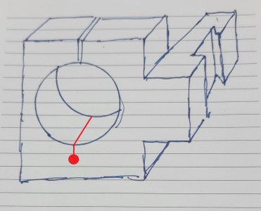
Question: how would you cut that inside slot?

A totally different approach but still viable is to cut it totally in half and make the far side a cap with 2 top and 2 bottom screws.
 
Last edited:
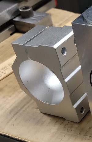
Funny how you get locked into ideas by history. Here is the bracket that came with the motor.

20220406_061418.jpg
 
Although I like this idea, I was planning to cut off the bottom leaving a 1/4", trimming the far side, far bottom and far top at 45° to 1/4", but leaving a top flange for screws. That would leave 4 weaker spots for bending.

Question: how would you cut that inside slot?
Milling down appears to result in a larger flexible or "hinge" area. Nice.

lol...after posting, I was wondering the same thing! The only thing that came to mind was drilling the hole and then a hack saw....take the blade off, place it through the hole and back together again. But then I realized that you have or will have a slot already so no need to disassemble the hack saw or just use the band saw? Maybe a little crude for this project. But then, my tool post holder is half a piece of pipe, that fits my die grinder, welded to a piece of keystock that fits my tool holder, and a pipe clamp to hold it together. :eek:

I like the look of yours. Very nice. I might put it on the list of things to do.

edit-I just read Post #84. Disregard everything I said....:p

No worries. All discussion is welcome. Discussion and brainstorming ideas results in improvements and also forms the basis of ideas for future projects.

Ya, I had thought of taking the blade off too. Then also realized its all just order of operations. The real problem is that hacksaws and bandsaws leave a rough surface. So I had planned to make the top cut with a slitting saw. But the more I think about it, the more I think a cap with 4 Screws is actually the best option because all four mating surfaces can be milled.

A separate cap can also be machined a bit easier.

Just wish I had thought of that earlier. The block would have been easier.

In fact, if the bracket that came with the motor was cut in half, I prolly didn't have to buy any stock at all.

Lots of lessons learned in this little project.

Heck, it may turn out that the spindle motor makes a very poor tool post grinder and the whole project was nothing but another failed experiment.

I hope otherwise.
 
Here's a trick. locate or make an arbor that is the same diameter as your hole (or close, it doesn't have to be perfect)

Clamp the workpiece in the vice with the arbor resting on top of the jaws. You can take successive cuts, making a concentric arc made of short lines that way - the result if very nice, and no thought or extra work to follow the inside circle...
I do most of them that way, quick and easy, after a few licks with a file, they look great. Just don't take a heavy cut!
 
This might not help much, but cuts are made across the part along the Y axis, and the part is indexed (or rotated, if you will) around the arbor, makinc a segmented OD cut in an arc to make very nice flexible clamping.....

View attachment 22848

Sometimes it takes me a while to fully digest such things.

It's a very cool idea that could be used for all kinds of things.

I see why the arbour isn't critical at all. All it does is maintain the spacing between the ID of the hole and the end mill. One could take as many cuts as desired to make it round or multi faceted.

I really like the possibility of a multi faceted result so I may try this. Unfortunately, my vice isn't deep enough to allow the bottom of the hole to be level with the top of the vice. Perhaps some bar stock on top of the vice just for spacing purposes.

Thanks @Dabbler !

 
Here is what I used for a tp grinder. I wanted a more powerful and hopefully sturdier one than what I thought the little electric or air die grinders are so I bought a 700 watt variable speed electric die grinder from princess auto.

I'm not sure yet how successful the grinder will be as I have only done a bit with it and the 1/4" shank stones I've bought ate terrible.

I really like the stones that @PeterT picture posted above. Where did you get those done? I think that is what I need.
View attachment 18974View attachment 18975
Don
I really like this approach. I have a die grinder and metal lying around.
How did this turn out?
 
Why can't you take a heavy cut?

Sometimes, depending on the part, there isn't much to hold onto, sometimes the part is long on the bore and short on width or its hanging down the side of the vise (not the best or strongest way to hold things), but the main reason is you don't know where along the work the clamping force is actually occuring. It might be even, or there might be a spot on the work a few thou thicker (something small enought that you can see it) where the force is concentrated. IF the later, when there is force on the work from the cutter, that creates a moment around where the clamping force is. This is very common but doesn't matter and isn't noticed when the work is supported from the bottom by vise or parallels or notched out angle block, but it can mess you up when taking an unsupported cut. I've have parts move using this technique when I was rushing (never a good idea).
 
Last edited:
Sometimes, depending on the part, there isn't much to hold onto, or its hanging down side of the vise (not the best or strongest way to hold things), but the main reason is you don't know where along the work the clamping force is actually occuring. It might be even, or there might be a spot on the work a few thou thicker (something small enought that you can see it) where the force is concentrated. IF the later, when there is force on the work from the cutter, that creates a moment around where the clamping force is. This is very common but doesn't matter and isn't noticed when the work is supported from the bottom by vise or parallels or notched out angle block, but it can mess you up when taking an unsupported cut. I've have parts move using this technique when I was rushing (never a good idea).

Gotcha. Makes sense.
 
Don
I really like this approach. I have a die grinder and metal lying around.
How did this turn out?

I considered this approach long and hard. The problem for me was the attachment to the motor body. That is what drove me to a ring clamp. I could have just turned one and then screwed it to a bar from the inside, but I worked myself all up worrying about up and down vibration harmonics accompanied by the inherent danger of a high speed grinding stone. Besides, I really wanted to try my hand at cutting a dovetail tool holder and a one piece arrangement just made sense to me. Whether the motor has enough oomph or not remains to be seen.

I'll prolly end up making an arbour for 3" outside stones, but where did you end up getting inside stones?
 
Don
I really like this approach. I have a die grinder and metal lying around.
How did this turn out?
Well I think the idea has some potential but I think I should have started with a better die grinder. The bearings in mine tend to be screechy so I wonder about their accuracy. The die grinder has speed control which is nice and has a collet holder system (although an oddball one). Mounting it on the tool post holder makes it easier to flip it to get it in different positions.
My biggest hold back on the whole thing is not having much for decent mounted stones yet. I haven't done much precision grinding with it because of that.
 
My biggest hold back on the whole thing is not having much for decent mounted stones yet. I haven't done much precision grinding with it because of that.

Please let me know when you do find some decent stones. I'm on the same hunt and not finding much of anything but what I know is junk!
 
Back
Top