Tool Post Grinder

Susquatch

Ultra Member
Administrator
Moderator
Premium Member
Not sure what is the RPM max. I assume 5500 or 6000 would be safe limit.

Seems fast to me.... Not for the stone itself but rather for my 1/4 shaft in an ER11 collet.

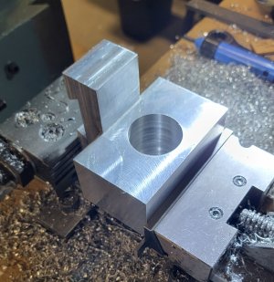
Yes the ER11 chuck was like .1mm smaller then the spindle. Same with the ER20. I could not have put them on, it was not even close to interference fit. So I reamed 8mm. Not sure whatever that was a great idea - I guess I see soon.

I would be too scared to try that mod. Basically, I am scared of high speed stones period. I use them just like everyone else, but I've seen 3 people in three separate accidents get chewed up bad by an exploding stone or wheel. I'm already ugly enough.

I still use them but usually well off to the side and still scared.

It may be perfectly safe, but I don't think I have the kind of guts it would take to make me modify a collet like that. Just me being a giant big sissy maybe but it is what it is. I don't like heights either.
 

Susquatch

Ultra Member
Administrator
Moderator
Premium Member
Funny that I'm so scared of modifying a collet. At the same time, I'm not scared of making a mandrel to hold a bigger 3 inch wheel (as was suggested by another member). That's my current plan so I can do external grinding without having to turn the spindle on an angle with all the side loads that creates.

For what it's worth, I'm also thinking about using cut-off wheels instead of stones. I think they will be just fine for the light loads I will put on them.
 

Tom Kitta

Ultra Member
You can either wear a face shield, put a shield on the grinder or both. We are not talking about a lot of energy here - 3in wheels are much smaller then 6in in your pedestal grinder. I can imagine the damage some of the 12", 2" thick weighting at around 20lbs+ wheels would do if they exploded at their 1800 rpm speed. That would be far more scary they a tiny 3" wheel weighting in at maybe 200 grams going off. Remember angular speed of the 12" wheel is same as the 3" wheel - i.e. similar SFM rating for cutting.

I am thinking of adding a small collar with a tiny shield or something like that, maybe held in place by just a clamp to make it both light weight and low profile.
 

Susquatch

Ultra Member
Administrator
Moderator
Premium Member
On hold while I setup the DRO.

Basically, I found myself thinking that a DRO would make the tool post grinder job a lot easier so I decided to do the DRO first. I'll probably do the Tool Post grinder before the two Z Axis DROs though. Almost certainly before the quill z DRO.

I may post a drawing of my Tool Post Grinder plans for everyone to shoot at in the meantime.
 

Susquatch

Ultra Member
Administrator
Moderator
Premium Member
So now that I have a working XYZ DRO, it's time to pickup where I left off on this project.

Here is my future grinder tool holder hiding inside this block of aluminium. The block is 4x4x4.5 It is all squared up and ready to machine in the features. It was an expensive block of aluminium by my standards so I want to save as much of it for future projects as I can.

20220403_170121.jpg

And this is what I think is hiding in there......

20220403_202122.jpg

As I sit here noodling the machining sequence, I find myself realizing how green I am at this stuff and wondering how others would tackle this.

Although I'd like to start right off cutting out the three blocks so I can save them for future projects, I think that might make it difficult to clamp and position the spindle holder for subsequent machining operations like boring the hole for the spindle motor, cutting the wedge for the tool post, slitting the holder to clamp the motor, and drilling and tapping the spindle clamp.

Any suggestions?

Design concept suggestions and criticisms are allowed too.
 

Dabbler

ersatz engineer
Here is what I'd do:

sus-toolholder.jpg

I'd use a bandsaw to take out 1 and 2, then refine the faces on the mill. You now have a good place to work hold. This is also a good time to mill the dovetail. The rest of the details on the dovetail (the height adjuster) can be done later.

Then take out the remaining piece and mill the last face (behind the bore) You can now hold it any which way, and be fine.
 

Susquatch

Ultra Member
Administrator
Moderator
Premium Member
Here is what I'd do:

View attachment 22740

I'd use a bandsaw to take out 1 and 2, then refine the faces on the mill. You now have a good place to work hold. This is also a good time to mill the dovetail. The rest of the details on the dovetail (the height adjuster) can be done later.

Then take out the remaining piece and mill the last face (behind the bore) You can now hold it any which way, and be fine.

YES!

That's sort of what I had in mind but you added the details I hadn't thought about - specifically to square up the leftover sides from those first two blocks on the mill BEFORE doing anything else, and then doing the dovetail right away.

Tomorrow! (I hope)
 

Susquatch

Ultra Member
Administrator
Moderator
Premium Member
Good progress today despite a few honey do's and a Kijiji run.

I cut the two bars off above and below the wedge with the band saw, then cleaned it all up on the mill, then cut the wedge groove, then tried it on my tool post. Looks GREAT!

20220404_105903.jpg

20220404_183225.jpg

20220404_183126.jpg


Tomorrow, I'll cut the right back off, drill out the motor hole,and maybe bore it to size.
 

Susquatch

Ultra Member
Administrator
Moderator
Premium Member
Gee, how did you manage to get that dovetail right the first time:D

There are three ways to learn.

From your mistakes,
From watching others,
From the mistakes of others.

I much prefer to put you in the second method. I am grateful to you for the learning opportunity.

That said, I had my tongue between my teeth the whole time. It's an expensive block of aluminium and I really didn't want to have to cut it off and screw two pieces together. I used my tightest tool holder as the model because I figured aluminium might get loose over time. An elephant could not have licked the smile off my face when that sucker slipped over the toolpost dovetail perfectly with zero room to spare!
 

YYCHM

(Craig)
Premium Member
There are three ways to learn.

From your mistakes,
From watching others,
From the mistakes of others.

I much prefer to put you in the second method. I am grateful to you for the learning opportunity.

That said, I had my tongue between my teeth the whole time. It's an expensive block of aluminium and I really didn't want to have to cut it off and screw two pieces together. I used my tightest tool holder as the model because I figured aluminium might get loose over time. An elephant could not have licked the smile off my face when that sucker slipped over the toolpost dovetail perfectly with zero room to spare!

Did you used the measure between pins technique to bracket the dovetail width?
 

Susquatch

Ultra Member
Administrator
Moderator
Premium Member
Today I tackled the 2 inch hole for the motor. First I cut off the big block on the right rear behind the motor.

20220405_084820.jpg

Many thanks to @thestelster for the tip to use a machine leveler to balance the saw vise.

Then I cleaned it up again on the mill.

20220405_104850.jpg

Still fits the lathe tool post perfectly!

20220405_110015.jpg

Next I used a two inch long by 1-7/8 annular cutter to rough out the motor mounting hole.

20220405_120838.jpg
 

Attachments

  • 20220405_120838.jpg
    20220405_120838.jpg
    467.9 KB · Views: 3

Susquatch

Ultra Member
Administrator
Moderator
Premium Member
Sorry, somehow I can't delete that last duplicate photo.

Anyway, after I cut the hole I hit a snag. Apparently a 2" boring bar has a wart on it. That makes it 2-1/8 diameter 3/4 of an inch or so above the cutting edge. That won't work. I need 2.055 inches down the whole hole - not just the first 3/4 inch.

So now I have to order a smaller boring bar which would delay the whole project a week or so, or cobble something up using a long bar in the 2" head. I don't like long tool stick outs.

20220405_122016~2.jpg
 

Susquatch

Ultra Member
Administrator
Moderator
Premium Member
@YYCHM & @trlvn, & @DPittman .

All three of those would have worked just fine. All very innovative solutions. Another member also privately volunteered to loan me the right size boring bar.

Before I saw your ideas, I went off line, sucked up some big air and went at it with a really long stick out on a honking big boring bar to clear the rest of the battle field. That worked just fine albeit slow to stop the chatter. Also had to slow down the mill a bit.

Here is the bored out holder.

20220405_135800.jpg

And here it is with the motor inserted. I still have to slit it and then drill and tap for two clamp screws. I also want to reduce the thickness all the way around so it will bend more evenly as it tightens down around the spindle motor. Might even end up with another piece of scrap aluminium for future projects.

20220405_135816.jpg

Anyway, the CEO is starting to get antsy about how long I've been out here so that's it for today.

Tomorrow I'll get to those tasks and might even spin it up!
 

Dabbler

ersatz engineer
Here's a trick. locate or make an arbor that is the same diameter as your hole (or close, it doesn't have to be perfect)

Clamp the workpiece in the vice with the arbor resting on top of the jaws. You can take successive cuts, making a concentric arc made of short lines that way - the result if very nice, and no thought or extra work to follow the inside circle...
 
Top