• Scam Alert. Members are reminded to NOT send money to buy anything. Don't buy things remote and have it shipped - go get it yourself, pay in person, and take your equipment with you. Scammers have burned people on this forum. Urgency, secrecy, excuses, selling for friend, newish members, FUD, are RED FLAGS. A video conference call is not adequate assurance. Face to face interactions are required. Please report suspicions to the forum admins. Stay Safe - anyone can get scammed.

Tool Post Grinder

Looking good. That spindle motor seems VERY quiet! What rpm was that running at? Most tool post grinding recommendations say to run work piece in opposite direction of grinder spindle but you were probably just trying things out as you didn't have a dressed stone either.
Nice machining on the holder.

Actually, you are being kind. I totally missed the opposite direction thing. In any event, I had thought the spindle motor was reversable but it isn't. At least not that I know of. I have not tried simply reversing the power leads. My lathe is reversable though. So that one is an easy fix either way.

I don't know what the spindle motor speed was. It's variable but the reostat isn't calibrated. That was running about 1/3 throttle. I have not even tried to measure it yet.

However, I did try running the motor a bit faster maybe 1/2. Given the unknown pedigree of the stone, i didn't want to go too fast. At 1/2 throttle it was even smoother.
 
Most tool post grinding recommendations say to run work piece in opposite direction of grinder spindle but you were probably just trying things out as you didn't have a dressed stone either.

I reversed the power wires on the spindle motor. That does indeed reverse its direction.

I should have been a little more confident of that given that the wires are polarized - a red wire and a black one.

This just means I need a double pull double throw switch in the motor power circuit so I can easily choose direction in the final setup.

I rigged up something temporary to measure speed with too. I put two counterbalancing pieces of black tape and reflective strips on the output shaft at different distances so only one triggers the tach and that seemed to be pretty stable at between 500 and 15,000 rpm. The setting I had it on in the previous video appears to have been around 5000 rpm. Prolly give or take 1000 or so. Although I really don't trust an electronic tachometer like this, that at least all seems reasonable to me. I might try it on the fan shroud too. I sure wish my kids didn't lose my mechanical tach. That thing was bulletproof. And, being non-digital, it never lied. But.... It could be a pain to use sometimes......
 
Last edited:
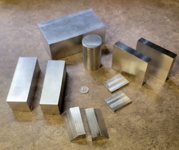
Oh yes, here are all the left over pieces from the block. I was reasonably careful to keep them as big and as useful as I could. Hopefully, they are all hiding a future part inside them that I will find someday. For now, they go into my piles of scrap and stock.

20220422_151319.jpg
 
I reversed the power wires on the spindle motor. That does indeed reverse its direction.

I should have been a little more confident of that given that the wires are polarized - a red wire and a black one.

This just means I need a double pull double throw switch in the motor power circuit so I can easily choose direction in the final setup.

I rigged up something temporary to measure speed with too. I put two counterbalancing pieces of black tape and reflective strips on the output shaft at different distances so only one triggers the tach and that seemed to be pretty stable at between 500 and 15,000 rpm. The setting I had it on in the previous video appears to have been around 5000 rpm. Prolly give or take 1000 or so. Although I really don't trust an electronic tachometer like this, that at least all seems reasonable to me. I might try it on the fan shroud too. I sure wish my kids didn't lose my mechanical tach. That thing was bulletproof. And, being non-digital, it never lied. But.... It could be a pain to use sometimes......
If you go onto the Dumore website, there is quite a bit of information regarding tool post grinding, https://www.dumoretools.com/resources
 
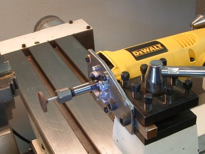
Here is what I used for a tp grinder. I wanted a more powerful and hopefully sturdier one than what I thought the little electric or air die grinders are so I bought a 700 watt variable speed electric die grinder from princess auto.

I'm not sure yet how successful the grinder will be as I have only done a bit with it and the 1/4" shank stones I've bought ate terrible.

I really like the stones that @PeterT picture posted above. Where did you get those done? I think that is what I need.
View attachment 18974View attachment 18975
Can you elaborate on your mount. Thanks !
 
Can you elaborate on your mount. Thanks !
I first turned down the aluminum housing of the die grinder from slightly tapered shape to perfectly round. I then made a steel cylinder that the machined housing fit into and then milled a square slot along the length of the cylinder and bolted in a 1/2" chunk of square steel that then would be held by a 1/2" QC tool holder.

Strange as it may sound, I used liquid electrical tape to glue in the machined die grinder into the cylinder. It seemed to hold well and is removable with heat.
 
I'll throw this one into the mix as well 220 volt, down the vevor rabbit hole today.

I believe spindle motors are 3 phase 400 cycle. As they say...."Mainly used for engraving machine or used with frequency converter."
 
I believe spindle motors are 3 phase 400 cycle. As they say...."Mainly used for engraving machine or used with frequency converter."

All three of mine only have two wires. They appear to be DC. The controller uses a duty cycle approach to speed control.

That's what my scope tells me. None of them have anywhere near the rated power no matter how you measure it.

Wish I knew more about them. I'd like to build a better power supply that could actually deliver the power the motor wants.
 
I first turned down the aluminum housing of the die grinder from slightly tapered shape to perfectly round. I then made a steel cylinder that the machined housing fit into and then milled a square slot along the length of the cylinder and bolted in a 1/2" chunk of square steel that then would be held by a 1/2" QC tool holder.

Strange as it may sound, I used liquid electrical tape to glue in the machined die grinder into the cylinder. It seemed to hold well and is removable with heat.
Thanks for the information!
I mickey moused my die grinder on the tool post last night for a quickie job. ( turned down a profile on a endmill )
That tapered cone of the die grinder was a real pain to deal with. So I will turn it round like you did, Any fancy or particular method to hold the housing in the chuck?

Thanks!
 
So, looking at the original Machifit (Banggood) motor with the ER11 collets -- I liked the idea of ER collets because it would allow the fitting of small endmills of various sizes -- wondering if anyone has tried using a small (2,3,4mm) endmill for cutting small slots such as keyways in steel work pieces ?
 
I had the same idea but backed off after seeing some disappointing installs, but it really depends on what you are trying to do. Will it grind metal & make the surface shiner? Yes. But hitting target diameters in the tenths range for things like bearing fit ups is more challenging. The spindle is only as accurate as the bearings its running in & these motor assemblies vary all over the map. So first thing is have a peek what you have. They vary from crappy roller bearing sitting in a rubber 'centering' ring (bad), to bearing set metal end bell (bit better), to double bearings (bit better) to AC (typically only on the brushless style where they specify inclusion & even those can have issues). Under any typical grinding load, things warm up. But I have seen nice operations like grinding tapered pins or needle valve seats where a smaller motor setup is much more convenient than a big TPG.

I'm personally thinking of a good brushless RC motor because the quality exceeds these by a long shot & even smaller form factor. The ER collet adapter can similarly be installed on shaft. Drive them with an ESC & servo tester speed control. Just have to select something that matches power supply & that's where I hum & haw.
 
For me, no thoughts of bearing fit-ups to "tenths". I'd be happy if I could cut a 1/8 or 5/32" keyway X 1" long in a shaft without having to remove it from the lathe. Of course, OD grinding would be a bonus too.
What got me going down this rabbit hole was a youtube video of a guy cutting ~ 1/8" keyways in small shafts on his lathe, his setup used a mini palm router -- which I thought was a great idea except you'd be limited to 1/4" shank tooling wheras the banggood motor had ER11 collets, opening up a wider range of tooling possibilities.
 
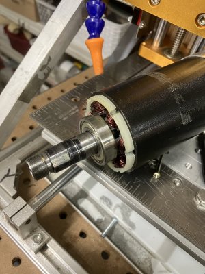
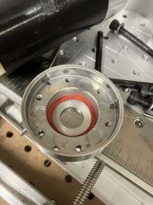
You folks are a very bad influence. Aghast with the idea that my spindle motor might not have bearings, I was forced to take it apart. I’m happy to say it has actual bearings, of a decent size, and pulling it apart took some effort so it appears to be a decent bearing fit-up.

And no, I haven’t mucked up the shaft. The black stuff is from a Sharpee, used to blacken the shaft so my optical tach could read spindle RPM.

IMG_3599.jpeg
 

Attachments

  • IMG_3600.jpeg
    IMG_3600.jpeg
    382.2 KB · Views: 7
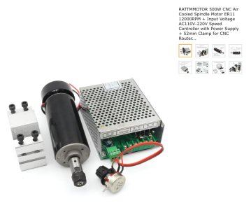
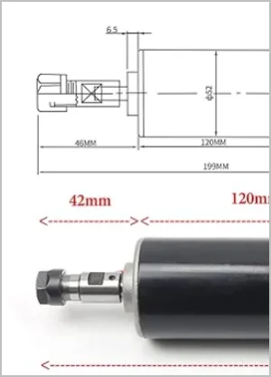
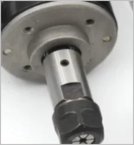
Is that the same motor? The Amazon link shows an output shaft (presumably running through bearings) & separate ER 'collar' mounted on shaft retained by set screw.
But your disassemble pic looks like an integral ER shaft running through motor housing/bearing(s)

1704125079451.png
1704125361036.png
 
Back
Top