• Scam Alert. Members are reminded to NOT send money to buy anything. Don't buy things remote and have it shipped - go get it yourself, pay in person, and take your equipment with you. Scammers have burned people on this forum. Urgency, secrecy, excuses, selling for friend, newish members, FUD, are RED FLAGS. A video conference call is not adequate assurance. Face to face interactions are required. Please report suspicions to the forum admins. Stay Safe - anyone can get scammed.

Other Sears Craftsman Garden Tractor

But it was fun. Really need to take a MIG welding course. The most disappointing part of the whole thing.

Amen! I'd like a few one-on-ones with anybody who makes good welds. I hate classrooms with a passion.

I would have made a clevis and pin instead of a hook and been done with it.

But as David says, if it works, who cares! You had fun. That's what really counts. Especially at your ripe old age!
 
Amen! I'd like a few one-on-ones with anybody who makes good welds. I hate classrooms with a passion.

I would have made a clevis and pin instead of a hook and been done with it.

But as David says, if it works, who cares! You had fun. That's what really counts. Especially at your ripe old age!
Unfortunately the hook is installed totally by feel through the small rectangular opening where the battery sits. Feel around until the arm that is connected to the PTO lever is found. Move PTO handle a bit to find that moving piece. Run fingers along it until 3/16" hole in end is found. Insert hook. Easier to describe than to actually do it the first few times.
 
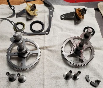
Exciting! Oil-Slinger/Governer and crankshaft seal arrived today. Both genuine B&S parts.

Tomorrow the CAMshaft kit will arrive. Not B&S. One I get it I'll decide if I just move the decompression mechanism over or use the entire shaft. I've seen on youtube that the far easy ones fail in places like the cam lobes coming loose or the gear breaking.

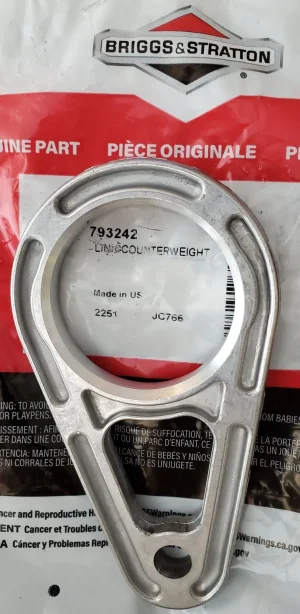
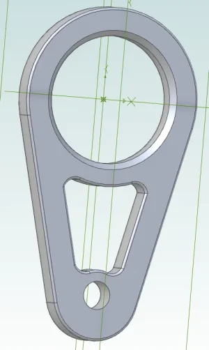
On Sunday the two balancer arms are scheduled to arrive. Before I install them I will do a CAD drawing with accurate dimensions. And then theoretically I could machine new ones if needed. The originals are just castings.
 
The CAM and seals arrived on time. Looks like the pin for the decompression flyweight is exactly the same and so it has the same weak point. Given that this kit was 1/3rd the price of a B&S name brand item I wonder if B&S fixed that weak point while the Chinese Clones still are made the old way.

1686180302156.webp
 
Yes a mig welder can sometimes cause more problems then it solves. I was having a problem with porosity the other day, I had changed to 100% argon from argon mixed, had to turn up the gas flow from what I had been using.
Went later to get some .025 in. tips, no luck, every one here had .030 or .035 in., and looked at me funny when I wanted .025. Found some .023 in. in Lethbridge, was doubtful, but welding supplier said they would work, and they do, hur ray.
Feed problems can be caused by, worn/dirty liner/wrong liner, worn/wrong feed rollers, wrong feed roller pressure, worn/wrong tip, worn tip holder, a big one is a kink/hard bend in feed cable/liner.
It appears/sounds as may have needed more wire feed to stop melting back into the tip. Sometimes trying to help is like looking into the crystal ball for answers. Any how some of the things I look for.
Good luck with the engine!
 
On mine the spool of wire would tighten enough to bugger up the feed so I replaced the nut with a locknut.
 
On mine the spool of wire would tighten enough to bugger up the feed so I replaced the nut with a locknut.
I was wonder if that was an issue for me too. Once I get the area cleaned up a bit and the motor out of the way I need to make a really good fume hood frame so I can use the welder and the foundry inside the shop. So good opportunity to do some more welding.
 
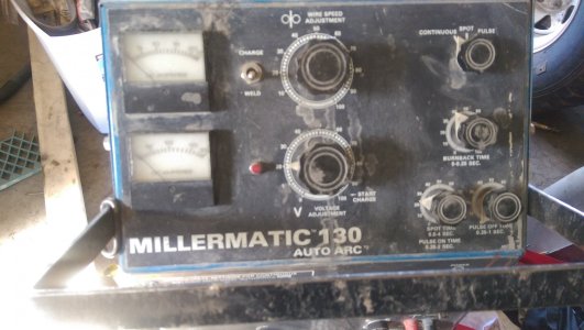
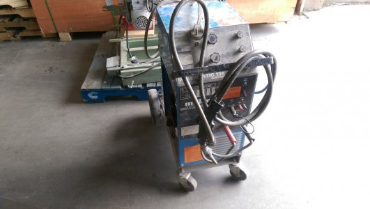
I had all sorts of issues with the wire feed on my Millermatic till I replaced the drive rollers and set the tension properly. Bought it at auction with unknown hours on the machine. I've never changed the liner and I've probably put 20 or 30 lbs of wire through it.
 
Liners can be the devil to deal with. We used a different liner when running alumunum wire, as could/would cause weld contamination with other wire types and vis versea.
Liners can get wear groove etc. in them over time and get metal bits, dirt etc. in them. Some times you can't even pull the wire through them by hand, let alone push it. That is a good way to check a installed liner, if you can't push the wire through it, don't expect the drive wheels to do it.
Any time you get a birds nest between drive wheel and enterence to liner/power whip, check for burn back into the tip first, then possible liner problems.
Another problem that can start to happen, is the getting slack in it, and coming off the spool, or abit of slack on the spool, causing the wire to cross over itself. Soon to happen bind up. A fine balance between the drive wheels able to pull the wire off spool and the spool tuning when the feed stops. As "Tom O" said he put a locking nut on.
Moderator(s) may want to put all this in welding area.
A new liner does not always solve the problem, more then once a new liner had to be changed again as there was something wrong with it. But we made sure we always had spares on hand, a production environment . And spare drive rollers too as per David_R8, aluminum rollers maybe different then steel wire rollers.
 
My little wire feed has a malady that I'm having trouble with. I quit using it a few years ago for some reason I had forgotten what it was. I tried to use it a couple days ago on some thin welding that I would have just burned a hole in with my stick....I was soon reminded why I quit the machine. It creates heat to weld with but the thing pulses on and off at 2 or 3 second intervals, it starts to weld and then shuts itself down almost immediately after starting a bead. I think it's tripping the duty cycle protection prematurely.
 
It creates heat to weld with but the thing pulses on and off at 2 or 3 second intervals, it starts to weld and then shuts itself down almost immediately after starting a bead.

Sounds like the perfect excuse to strip it down for parts and buy a nice Tig/MIG Combo.
 
Wow, you have pulse on your mig historicalalarms, most of us have to pay extra for that. Not sure what to look for there, could try unplugging, remove cover, look for a loose connector, or even a short, sometimes caused by a piece of welding wire that's got into the works. Yes it does happen, have found rod stubs in units. If it has a cooling fan, see if it runs. Other wise try carefully blowing unit out, amazing how much dirt and dust can get in them, a lot from angle grinder spray landing around ,in ,on them.
Look at it this way, it's not working now, hard to make it worse. Oh, wait a minute, was that magic smoke!
I feel the pain, the suitcase tig I was given, she no work, found out when I thought I would learn to tig weld this spring. Maybe why it was given to me.
I can remember doing a cursory check of loosening all the assessable connections and re-tightening them but I haven't gone deep enough inside yet.

Tom , This is a very rudimentary machine (Century faceplate ) that only has a wire speed dial & an amperage dial and those dials are not infinite setting dials.
 
The last of the parts have arrived. These look a tad better than the bits and pieces I pulled out.
So first thing is measure them so if I wanted to make my own I could do that.
Second, figure out which side the large hole bevel is supposed to go.
 

Attachments

  • CountershaftRods.webp
    CountershaftRods.webp
    198.7 KB · Views: 7
The last of the parts have arrived. These look a tad better than the bits and pieces I pulled out.
So first thing is measure them so if I wanted to make my own I could do that.
Second, figure out which side the large hole bevel is supposed to go.
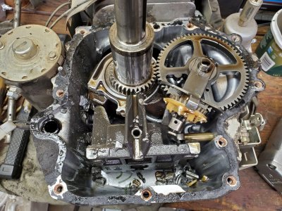
So here's what I think. This is a vertical shaft engine that so we're really looking up at it from the bottom.
CrankcaseWithBits.jpg

It's clear that machined section is facing up since we can't see it. I'm guessing that's to capture the splashed oil and let it seep between the arm and the crankshaft for lubrication.

The one underneath was destroyed with nothing left so no pictures or knowledge of how it was installed. I'm guessing the bevel will also be up for the same reason. Capture the oil to let it drain downwards along the bearing.

Does that make sense?
 
I think the dimensions of this sketch are close enough as long as both pieces are made from the same drawing. The originals are die cast and I believe the channels are just there to reduce the amount of metal that really isn't needed for strength. Really no point in carving grooves on both sides.

I'd likely just mill these out of 6061-T6.

1686554692592.webp
 
Back
Top