RF30 Basement Install

Dusty

(Bill)
Premium Member
Your terminology works for me:p Can you not modify the collet chuck to match your spindle and not bother with a mounting plate? What size is the chuck you have that mounts directly on the spindle?

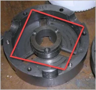
There are probably a few interchangeable words for this. 'Boss' is often used to mean any kind of protruding feature. I see it used often in CAD circles for this kind of thing & a few chuck/backplate references. Sometimes it doesn't have a name, just a dimension, 'Recess' or 'pocket' might be a good word for the negative mating surface.
https://en.wikipedia.org/wiki/Boss_(engineering)

Thanks for your prompt comments @PeterT, I can work with 'Boss' and 'recess or pocket' make sense to me. Sometimes I read more into the equation than what's really there. Back to aging. LOL
 

Dusty

(Bill)
Premium Member
Your terminology works for me:p Can you not modify the collet chuck to match your spindle and not bother with a mounting plate? What size is the chuck you have that mounts directly on the spindle?

Hey Craig, my lathe is a Craftex B2227L and my spindle has a 127mm diameter face plate attached with 108mm Boss. My collet chuck form the
https://accusizetools.com/ catalog, item #ER3210100, page 29, with a recess of 72mm. I shudder at the thought of modifying the existing spindle face plate. Additionally my 3J is a blonde hair under 5" diameter and my 4J is a Brunet hair over 5" diameter, both have a 108mm recess/pocket base.

That said, for me the safest way ahead is fasten a second face plate with 108mm recess/pocket on the one side then turn a 72mm Boss on the opposite. Might be a bit of a tricky project getting alignment spot on.
 

YYCHM

(Craig)
Premium Member
Hey Craig, my lathe is a Craftex B2227L and my spindle has a 127mm diameter face plate attached with 108mm Boss. My collet chuck form the
https://accusizetools.com/ catalog, item #ER3210100, page 29, with a recess of 72mm. I shudder at the thought of modifying the existing spindle face plate. Additionally my 3J is a blonde hair under 5" diameter and my 4J is a Brunet hair over 5" diameter, both have a 108mm recess/pocket base.

That said, for me the safest way ahead is fasten a second face plate with 108mm recess/pocket on the one side then turn a 72mm Boss on the opposite. Might be a bit of a tricky project getting alignment spot on.


Ya, don't modify your spindle that's for sure:eek: Thought maybe opening the collet chuck recess to match the spindle might be an option, but I see the collet chuck you got may be a little too small for that.

A little slop in the registration fitment would allow you to bump the collet chuck to minimum runout. Did that on a chuck mounting plate I had to turn the registration boss on. Worked well.
 
Last edited:

Dusty

(Bill)
Premium Member
Ya, don't modify your spindle that's for sure:eek: Thought maybe opening the collet chuck recess to match the spindle might be an option, but I see the collet chuck you got may be a little too small for that.

A little slop in the registration fitment would allow you to bump the collet chuck to minimum runout. Did that on a chuck mounting plate I had to turn the registration boss on. Worked well.

Hey Craig, shall think on that option, might require my shaving a thousand from the 72mm collet Boss when finalizing set up.
 

YYCHM

(Craig)
Premium Member
I have the same problem..... I'm using threaded 'nuts' which removed some of the bulk, but its still clumsy. and just when I think I have it under control, the nut will catch the table locks.

so it would appear a smaller chuck or a smarter way of attaching it is required. I'm watching your progress so I can mimic your solution.


I might have a solution to this issue......

Plate14.JPG

If one was to mill a step such that a hex head bolt would fit under the chuck, shaped as I have marked out here, the T-Nuts can be moved in board and the bolts tightened with a wrench. What do you think?
 

RobinHood

Ultra Member
Premium Member
That could work. You’ll need to check that the modification of the chuck does not interfere with the fasteners which hold the two halves together or the pinions or the scroll itself.
 

YYCHM

(Craig)
Premium Member
That could work. You’ll need to check that the modification of the chuck does not interfere with the fasteners which hold the two halves together or the pinions or the scroll itself.

Not messing with the chuck, I would mod the mounting plate.
 

RobinHood

Ultra Member
Premium Member
Ah, ok. So you’d basically countersink the hex bolt deep enough so when tight, the head is below the surface of the plate. Plus you’d mill away enough material to get your spanner on to tighten the bolt. You could always reduce the bolt head height a bit too - and the thickness of the spanner to match.

Have you had this chuck apart? Reason for asking: would there be enough material in the sidewall that you could make the red circled holes through holes and use 3 long bolts all the way through into the T-nut in the RT slot?

F1F97217-C240-4E45-9FB7-9DD5586C4D97.jpeg
 

RobinHood

Ultra Member
Premium Member
Another question: does your RT have a center hole? If so, you could make a pin to fit into that hole and also machine a matching hole into the mounting plate. That would transfer any radial loads from the chuck (through the register on the plate) to the pin and directly into the RT. You could then reduce the fastener size you use to hold the plate/chuck combo onto the RT. Might give you some more options as well.
 

YYCHM

(Craig)
Premium Member
Have you had this chuck apart? Reason for asking: would there be enough material in the sidewall that you could make the red circled holes through holes and use 3 long bolts all the way through into the T-nut in the RT slot?

Apart.JPG

Hmmmmm, it's a 4 slot RT, not 3.
 
Last edited:

YotaBota

Mike
Premium Member
What about using countersunk socket headscrews and V grove the slots so the screw head is just below the level of the chuck. That way you could start the screw in the t-nut and slide it right up to where the hex key meets the chuck then when the chuck is centered tighten down the screws.
you could make a pin to fit into that hole and also machine a matching hole into the mounting plate
Good point.
 

YYCHM

(Craig)
Premium Member
Well.... this might just work....

Plate15.JPG

There isn't much meat left at the bottom of the recess, but with 4 of them I think it should be ok. A thinner bolt head, a washer and a thinner spanner would help.
 

PeterT

Ultra Member
Premium Member
Now that I see the chuck apart, I'd be tempted to find a spacing that doesn't intersect jaw or key pinion, drill 4 holes through both lip sides & bolt directly through chuck into RT tee slots. No more middle man plate. That's probably how some of those front mount chucks work.

I almost always prefer a 4-jaw on RT. By the time I monkey around getting 3J close I may as well dial in the part exactly. Then you can grip odd or rectangular shapes too.
 

Attachments

  • EDT-2021-10-20 11.27.20 PM.jpg
    EDT-2021-10-20 11.27.20 PM.jpg
    28.2 KB · Views: 4

Dabbler

ersatz engineer
@PeterT Most RTs have a bored centre (cylindrical or MTx). RTs that have a manufacturer's 3J chuck usually have a registration boss on the back of the chuck for mounting the chuck concentric to the rotation. Does yours have this featiure?
 

PeterT

Ultra Member
Premium Member
@Dabbler, yes my RT has a MT taper in the center & the chucks typically have a recess to mate to a backplate boss. That recess theoretically makes the chuck body concentric to its male counterpart because (at least we hope) the recess was machined first, the jaws then inserted & ground. So good chucks will be close. I'm just saying in reality, the jaws & scroll have their final say in how concentric the part itself will be independent of the recess. I've also seen chucks with MT arbors on the back, but I'm not clear if the have any means to stay put rotationally other than friction.

What I've done, only because I have the doo-dad, is leave the chuck/plate snug but slightly loose on the RT table. Drop an MT test bar into the RT hole (MT on one end, cylindrical on the other) very lightly clamp the jaws on the bar & then secure the plate+chuck in this position. Release the test bar & ready for action. Even this is isn't bulletproof because the jaws are only registering on this particular bar diameter & may be different on another diameter (I think scroll accuracy?). And this may not lend itself to reversed jaws (mouth open) depending on the chuck.

Another homebrew system I've seen is the plate has a circular recess for the chuck OD plus some adjustment allowance & 4 radial set screws that act as a 'Set-Tru' principle. But it still required axial bolts through the chuck body into RT tee slots to retain the chuck axially. And the side loads are concentrated on the small area of set screws vs the boss/recess. For that effort maybe consider dedicating a chuck to the RT but I think the fellow wanted to do turning in the lathe, pop the chuck off with part still in & onto RT to preserve concentricity.

It's all this fiddle farting that makes me think its viable to mount a 4 jaw roughly concentric by eyeball & spend your time dialing in the part itself. But it all depends on the job. If you aren't thou chasing then do what is easiest. Also don't gronk on the test bar obviously, its hardened but bite marks would be a bad thing.

1634834066320.png
 

YYCHM

(Craig)
Premium Member
More progress today....

Plate16.JPG


I'm loving that carbide end mill, it just goes and goes..... This was all side milling 1/4" DOC, wasn't even paying attention to side DOC, just make a pass and bump her over. All mill to the line stuff.

Plate17.JPG

Weird eh... No where near symmetrical....:rolleyes:

2MTTaper.JPG

I'm thinking about turning this drill chuck 2MT arbor round to use as a RT centering jig. Do you think that will work or is it too hard?
 
Last edited:

YYCHM

(Craig)
Premium Member
Ends up you can turn a hardened and ground 2MT taper down.

2MTTaper1.JPG

The very end is hard but further back not so much. Tool needs sharpening now LOL.

2MTTaper2.JPG

Centering the table to the RT with the 2MT taper....

Chuck.JPG

I assume this is a legit way to center the chuck on the centered RT. With the mounting plate loose, I clamped the jaws onto a 3/8" tool shank and then tightened down the plate hold down bolts.

@kevin.decelles this arrangement does tuck the T-Nuts in sufficiently.

Table.JPG

At @Dabbler 's suggestion I scooched the vise over in order to mount the RT but I'm having my doubts about this arrangement. Leaving the chuck attached to the RT is definitely a no-go. As well, the left hand side of the table has limited in board travel due to the power feed. Hmmmmm..... Maybe a little to crowded I think.
 
Last edited:

Dabbler

ersatz engineer
The idea is to skootch your vise over 4-5" off centre. This gives you the *opportunity* to mount the RT without moving your vise away (most of the time). No one leaves their RT on their mill full time. It's just in the way.

This is fine for most small work. Once the job gets bigger, you need the RT in the centre of the table anyway, so the vise has to go.
 
Top