-
Scam Alert. Members are reminded to NOT send money to buy anything. Don't buy things remote and have it shipped - go get it yourself, pay in person, and take your equipment with you. Scammers have burned people on this forum. Urgency, secrecy, excuses, selling for friend, newish members, FUD, are RED FLAGS. A video conference call is not adequate assurance. Face to face interactions are required. Please report suspicions to the forum admins. Stay Safe - anyone can get scammed.
-
Several Regions have held meetups already, but others are being planned or are evaluating the interest. The Calgary Area Meetup is set for Saturday July 12th at 10am. The signup thread is here! Arbutus has also explored interest in a Fraser Valley meetup but it seems members either missed his thread or had other plans. Let him know if you are interested in a meetup later in the year by posting here! Slowpoke is trying to pull together an Ottawa area meetup later this summer. No date has been selected yet, so let him know if you are interested here! We are not aware of any other meetups being planned this year. If you are interested in doing something in your area, let everyone know and make it happen! Meetups are a great way to make new machining friends and get hands on help in your area. Don’t be shy, sign up and come, or plan your own meetup!
You are using an out of date browser. It may not display this or other websites correctly.
You should upgrade or use an alternative browser.
You should upgrade or use an alternative browser.
RF30 Basement Install
- Thread starter YYCHM
- Start date
Can you just swap the wires and leave the switches in place? It might save you some grief trying to put everything back together.
It's tight in there. You would have to remove the switches to disconnect and swap the wires so it was just easier to swap the switches around.
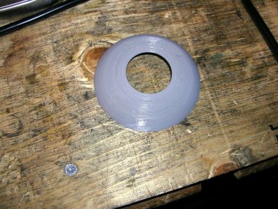
Your cover in the making.
View attachment 13991
David,
Did this get mailed out yet? Got any tracking info for it?
Craig
Excellent. Now don't be like me and just sand it down and stick it on... give it a coat of latex primer and top coat.
Otherwise it will be grimy in two seconds.
Excellent. Now don't be like me and just sand it down and stick it on... give it a coat of latex primer and top coat.
Otherwise it will be grimy in two seconds.
Looks like I need to relieve the hole a little. How does it attach to the power feed?
Mine just slips over and is held by friction.
Don't over-relieve the hole...
Ok, so the cover spins then?
Yup, it's a friction fit over the brass gear hub.Ok, so the cover spins then?
I acquired a 6" HV Rotary Table, nothing special, just your plain jane BB RT. Ordered indexing plates on Amazon that were delivered within a week from India. The plates fit ok, but had to make up a mounting collar for the plates in order to get the crank handle to work acceptably. Since I have a 5" 3J chuck sitting on the shelf under my lathe doing nothing, I decided to make an adapter plate....
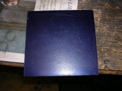
Starting with 6" X 6" X 1/2" plate.
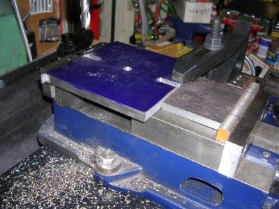
The setup on my mill turned out to be a bit of a challenge. I decided to drill a centering hole and mill mounting slots in one go.
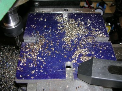
Finally, with 4 slots, but not after having the plate move in the vise once @@@#$%$%&*(()()
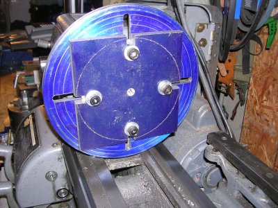
Here it is mounted on my face plate (Thanks @Brent H ). Initial thoughts were to turn her round on the lathe, but milling it round on the RT is another option.
Suggestions? Lathe or RT?

Starting with 6" X 6" X 1/2" plate.

The setup on my mill turned out to be a bit of a challenge. I decided to drill a centering hole and mill mounting slots in one go.

Finally, with 4 slots, but not after having the plate move in the vise once @@@#$%$%&*(()()

Here it is mounted on my face plate (Thanks @Brent H ). Initial thoughts were to turn her round on the lathe, but milling it round on the RT is another option.
Suggestions? Lathe or RT?
Last edited:
I'd cut off the corners in the bandsaw first and finish on the rotary table.
historicalarms
Ultra Member
Craig, I'm curious, did those elevated vise jaws that allow you to use the full size of the vise slide with spacers involved come factory with the vise or was it a personal addition....if personal, very well done. I would have never thought of doing that until I seen it here and many times I needed "just a little more jaw opening" to grab something.
I'm with john...cut the corners off first bandsaw, cut-off saw or third choice, torch. Actually torch is quite viable, just bench grind the hardened outside edge a bit with bench grinder to ease pressure on lathe or mill cutter.
I'm with john...cut the corners off first bandsaw, cut-off saw or third choice, torch. Actually torch is quite viable, just bench grind the hardened outside edge a bit with bench grinder to ease pressure on lathe or mill cutter.
Last edited:
Craig, I'm curious, did those elevated vise jaws that allow you to use the full size of the vise slide with spacers involved come factory with the vise or was it a personal addition....if personal, very well done. I would have never thought of doing that until I seen it here and many times I needed "just a little more jaw opening" to grab something.
I think it's a factory feature. @Dabbler can you comment?
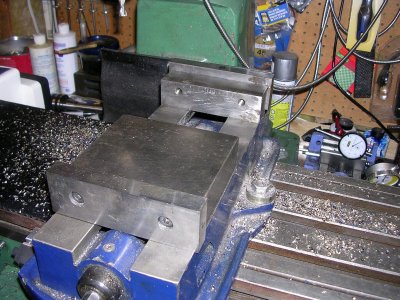
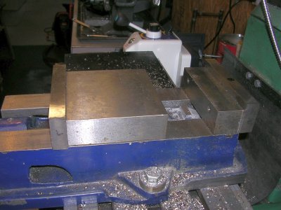
The jaws are secured with recessed hex cap screws that allow the jaws to be moved to the outside of the fixed and moving portions of the vise.
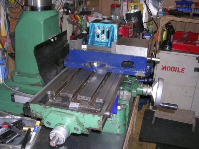
Normally I use it in this configuration with the jaws on the inside.

