• Scam Alert. Members are reminded to NOT send money to buy anything. Don't buy things remote and have it shipped - go get it yourself, pay in person, and take your equipment with you. Scammers have burned people on this forum. Urgency, secrecy, excuses, selling for friend, newish members, FUD, are RED FLAGS. A video conference call is not adequate assurance. Face to face interactions are required. Please report suspicions to the forum admins. Stay Safe - anyone can get scammed.

RF30 Basement Install

This is an interesting thread, i moved a LC 30A into the basement last year and plan in the future to go with a 3phase motor and VFD. Absolutely hate changing speeds on this thing.
Yup, I've got a machine that j would someday like to get on vfd 3 ph also to avoid the belt changes but I don't have the willingness or know how to figure this stuff out myself. I am electrically challenged. I will benefit from the experience of the "pioneers" in this thread.
 
This is an interesting thread, i moved a LC 30A into the basement last year and plan in the future to go with a 3phase motor and VFD. Absolutely hate changing speeds on this thing.

I have an LC30 mill also. I switched it to 3-phase power last year and it’s been brilliant. Changing speed is now a simple turn of a dial.


Sent from my iPhone using Tapatalk
 
The 3 PH motor shaft is almost 1/2" shorter than the 1 PH motor. So I had to mount the 3 PH motor higher on the mounting plate (I may have to lower it some, time will tell). Still, the motor pulley had to be raised from it's natural resting place to line up with the idler pulley and spindle pulley. I didn't like this situation so I decided to make a spacer for the motor pulley to rest on......

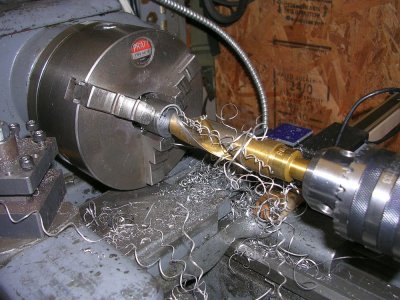
BUSHING1.JPG


1" round stock drilled out to 7/8".

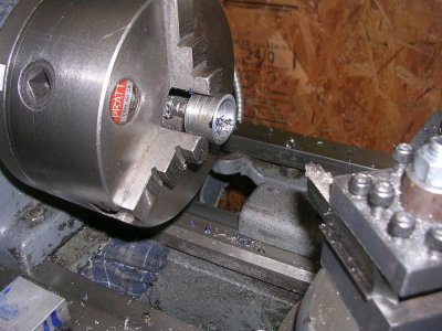
BUSHING2.JPG


Turned down to the required length...

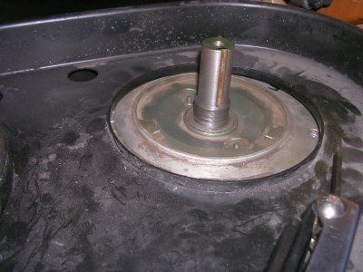
BUSHING3.JPG


And installed on the motor shaft.
 
Further to my pulley spacer, I noticed that the spacer wasn't spinning with the motor shaft, so something had to be rubbing on something with that arrangement.

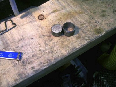
SPACERPLUG.JPG


So I replaced the spacer sleeve with a spacer plug that fits in the pulley bore and holds the pulley up to the required height. Simple eh... Don't know why this solution didn't occur to me in the first place:rolleyes:
 
Last edited:
Your spacer was probably rubbing on the bearing shield or dust seal. If you were to chamfer that end so that the OD matches the inner race of the bearing, you could use the spacer and it would turn with the motor shaft.

How is the plug held in the pulley bore? Additional set screw?
 
Ok, so I am missing something here then.

I thought the plug is in the pulley bore top. When fastened to the pulley, would allow the pulley to slide down the shaft until the plug bottom makes contact with the motor shaft. And no lower. Thus giving you the peace of mind that you are after by preventing the pulley to slip all the way down the shaft and cause belt alignment problems. Do I not understand the purpose of the plug?

That is what your spacer ring would do - only from the bottom.

You have it right. The pulley bore is blind, so the plug takes up the space between the top of the motor shaft and the end of the pulley bore.
 
I'm liking this VFD set up......

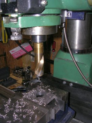
DRILLING.JPG


I drilled to 1" (in steps) running at 30 HZ no problem. 30 HZ translates to 400 RPM. Currently belted for 770 RPM with the VFD set for a range of 30-90 HZ. That translates to 400-1200 RPM. I'll try milling in the low and high RPM range tomorrow.
 
Have you got reverse working?

I do now.....

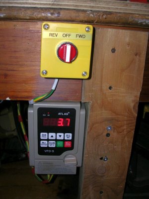
FWDREVSWITCH.JPG


Had to go the hard wired route.

There are 5 wired options.

run-fwd
run-rev

jog-fwd
jog-rev

fwd-rev switch

I only implemented run-fwd and run-rev. Not a clue what "fwd-rev switch" would accomplish???

In any event it does what I wanted it to do now...
 
I do now.....

View attachment 12524

Had to go the hard wired route.

There are 5 wired options.

run-fwd
run-rev

jog-fwd
jog-rev

fwd-rev switch

I only implemented run-fwd and run-rev. Not a clue what "fwd-rev switch" would accomplish???

In any event it does what I wanted it to do now...

Very good! What are the details on that switch? Where did you get it? Do you have a link to specs?

I take it that when you turn your new switch, the motor immediately starts turning in the indicated direction? IOW, you don't have to select a direction and then use the Run/Stop buttons on the VFD to start the motor running? Just a WAG, but I think the "fwd-rev switch" circuit might work the latter way.

Also, I think on your 3-ph motor, you can immediately flip from forward to reverse without waiting for the motor to come to a stop. I believe it should very quickly stop and immediately start turning the other direction. Such behaviour isn't possible with a single phase motor due to the way the start circuit works.

Craig
 
Also, I think on your 3-ph motor, you can immediately flip from forward to reverse without waiting for the motor to come to a stop. I believe it should very quickly stop and immediately start turning the other direction

That is true - won’t hurt the motor a bit.

The VFD might not like it at all because of the huge back EMF.

That’s another reason for a RPC - it can take instantaneous reversing of the load motor.
 
Very good! What are the details on that switch? Where did you get it? Do you have a link to specs?

I take it that when you turn your new switch, the motor immediately starts turning in the indicated direction? IOW, you don't have to select a direction and then use the Run/Stop buttons on the VFD to start the motor running? Just a WAG, but I think the "fwd-rev switch" circuit might work the latter way.

Also, I think on your 3-ph motor, you can immediately flip from forward to reverse without waiting for the motor to come to a stop. I believe it should very quickly stop and immediately start turning the other direction. Such behaviour isn't possible with a single phase motor due to the way the start circuit works.

Craig

Nothing special about the switch actually.

https://www.princessauto.com/en/3-position-select-switch/product/PA0000700324

There is a setting in the VFD that sets the run command channel to panel, terminal, or comms? (it has a Modbus port?). Once you set the command channel to anything but panel, the front panel run, stop, and jog buttons cease to function. There are 5 low voltage terminals that register 12V against ground. I assume only one should be active at a time. There are 25 options that you can configure each terminal to perform but some don't make sense. For example "Key runs" vs "Wire runs forward". What key if the front panel is disabled? If you set the run command channel to panel then the terminals are ignored.

Soooo...… dunno.
 
Last edited:
Craig, did you get all the functions on your VFD working?

Just FWD and REV, adding more would required a more sophisticated switch than PA sells or multiple switches.

What are you trying to do?
 
Last edited:
Back
Top