• Scam Alert. Members are reminded to NOT send money to buy anything. Don't buy things remote and have it shipped - go get it yourself, pay in person, and take your equipment with you. Scammers have burned people on this forum. Urgency, secrecy, excuses, selling for friend, newish members, FUD, are RED FLAGS. A video conference call is not adequate assurance. Face to face interactions are required. Please report suspicions to the forum admins. Stay Safe - anyone can get scammed.

RF30 Basement Install

So after much dithering I finally decided to convert my mill to 3 phase with VFD speed control.
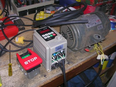
VFDSTUFF.JPG


Pretty much have everything I need now

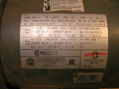
2 HP 3 PH motor $60 from Kijiji
4 HP VFD $75 from Amazon
ESD switch $18 from BB
12' of 14AWG 4 strand electrical cord $23 from Home Depot

I was going to wire the ESD into the singe phase side and use it double duty as an ESD and an on/off sw for the VFD but I noticed it's capable of handling 3 phase so now I'm not sure what to do? Should I wire it to the 3 phase side or to the single phase side? Do you think it really matters?

Craig
 
Last edited:
So after much dithering I finally decided to convert my mill to 3 phase with VFD speed control.

View attachment 11707

Pretty much have everything I need now

2 HP 3 PH motor $60 from Kijiji
4 HP VFD $75 from Amazon
ESP switch $18 from BB
12' of 14AWG 4 strand electrical cord $23 from Home Depot

I was going to wire the ESD into the singe phase side and use it double duty as an ESD and an on/off sw for the VFD but I noticed it's capable of handling 3 phase so now I'm not sure what to do? Should I wire it to the 3 phase side or to the single phase side? Do you think it really matters?

Craig
I have limited experience with VFDs but have read that repeated off/on cycles is hard on the electronics. I leave mine on all the time and use a DPDT switch mounted on the mill and wired to the low voltage side of the VFD to control rev/off/frwd.
 
I have limited experience with VFDs but have read that repeated off/on cycles is hard on the electronics. I leave mine on all the time and use a DPDT switch mounted on the mill and wired to the low voltage side of the VFD to control rev/off/frwd.

This VFD has two fans that would be running continuously if I leave it on all the time.

Another thing...… are you set up for decelerated stop or free stop? This VFD is set to decelerated stop and I think I would prefer free stop.
 
This VFD has two fans that would be running continuously if I leave it on all the time.

Another thing...… are you set up for decelerated stop or free stop? This VFD is set to decelerated stop and I think I would prefer free stop.
The fans on mine only run when some parameter is hit such as temp or something.
I have some braking set, maybe 3-4 secs but because there is only the internal brake resistor if the braking is set too fast it just kicks out and nothing happens.
 
Well..... I can't believe this.... after all my planning the motor pulley doesn't fit the 3 phase motor :mad: 0.0085" difference in diameters. The 1 phase motor measures 0.865 and the 3 phase motor measures 0.8735. Different size keys as well:mad:

To add insult to injury I only discovered this after struggling to dismount the 80 lb single phase motor. I had attempted to remove the pully to check before dismounting the motor but it wouldn't come off. Once the motor was off (Phew), I realized (remembered) there are two set screws and off she came with nothing more than a tug:oops:

So now what to do:confused:
 
So the pulley is too small for the 3-phase motor?

If that’s the case can it be bored slightly larger?
Sent from my iPhone using Tapatalk
 
Recommend sourcing or making new pulley . Keep orig pulley with orig motor —. That is your fallback plan

I just went through this with my drill press. 20mm shaft on original , 19mm shaft in surrogate.

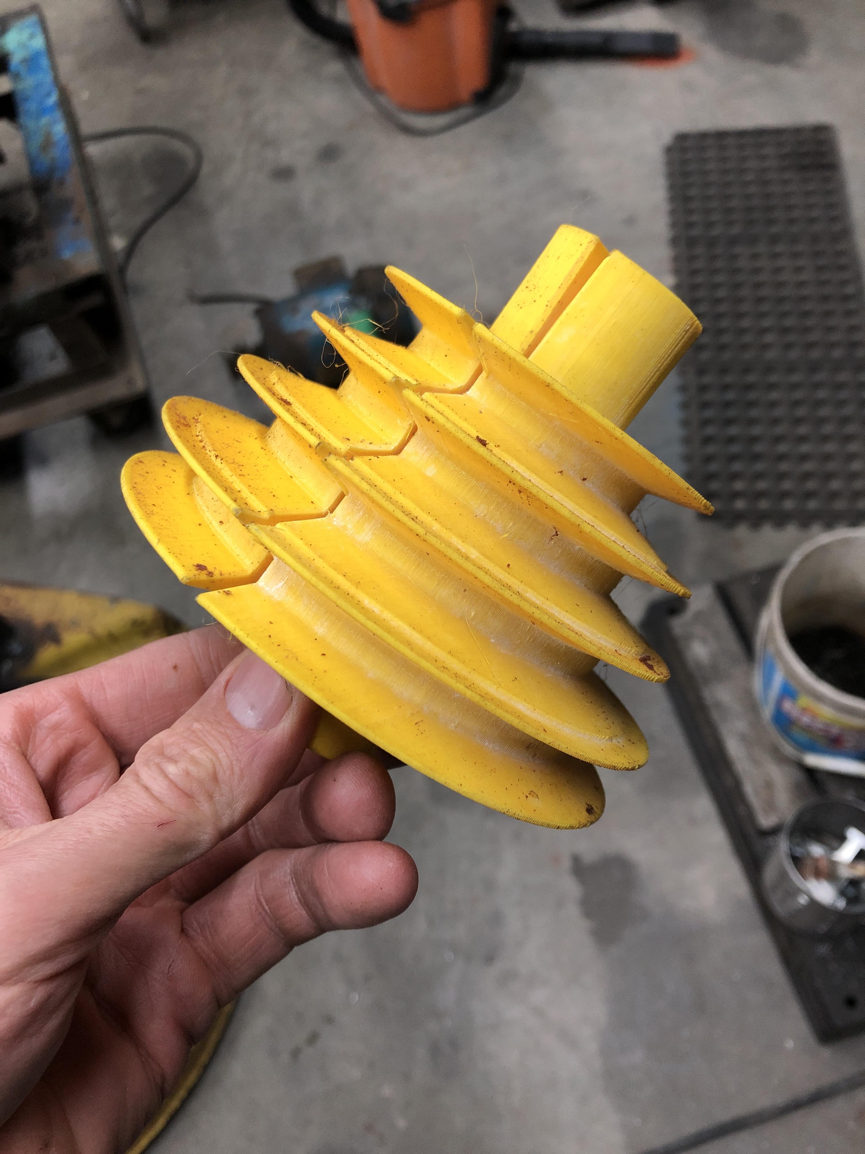
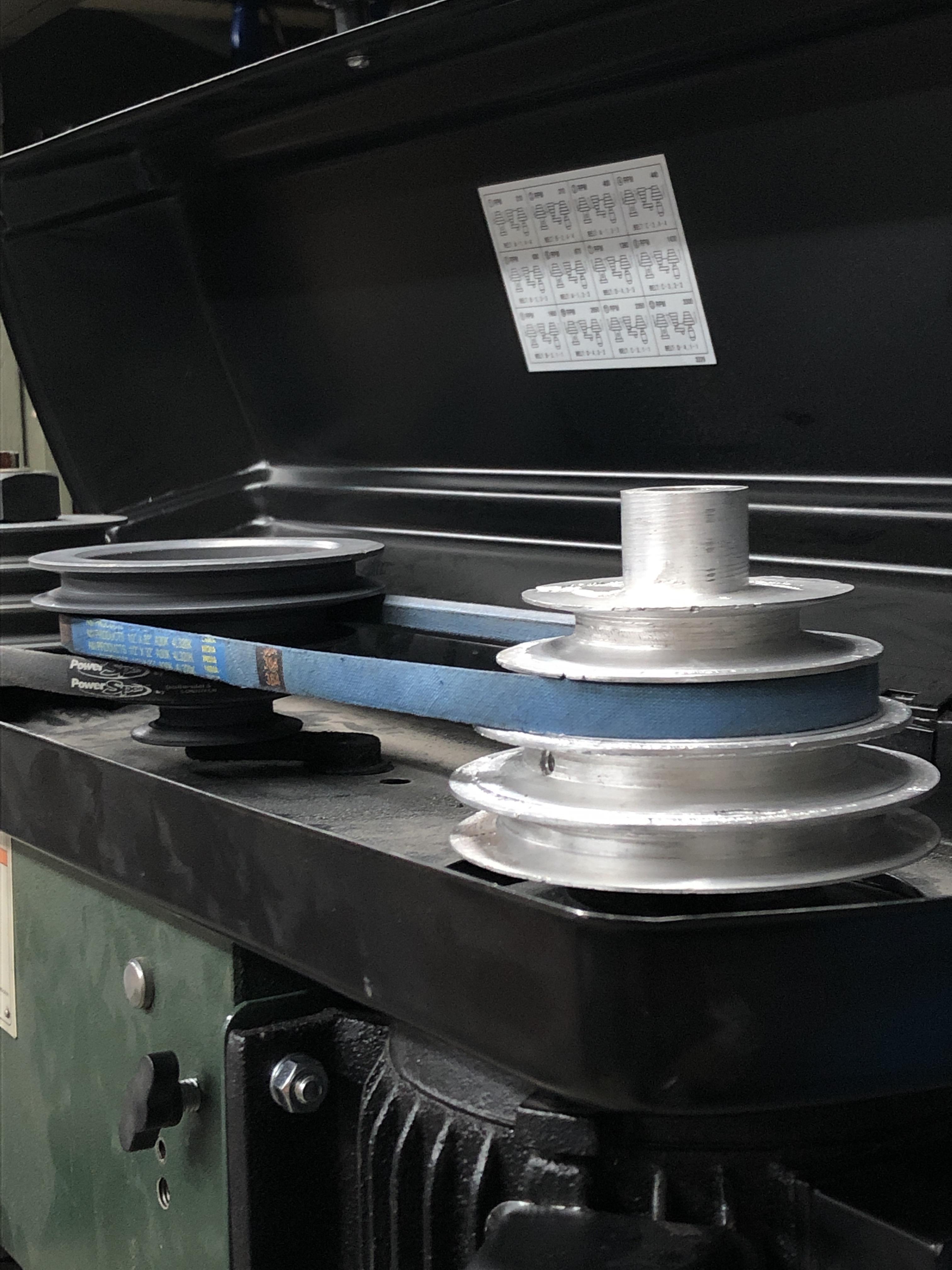
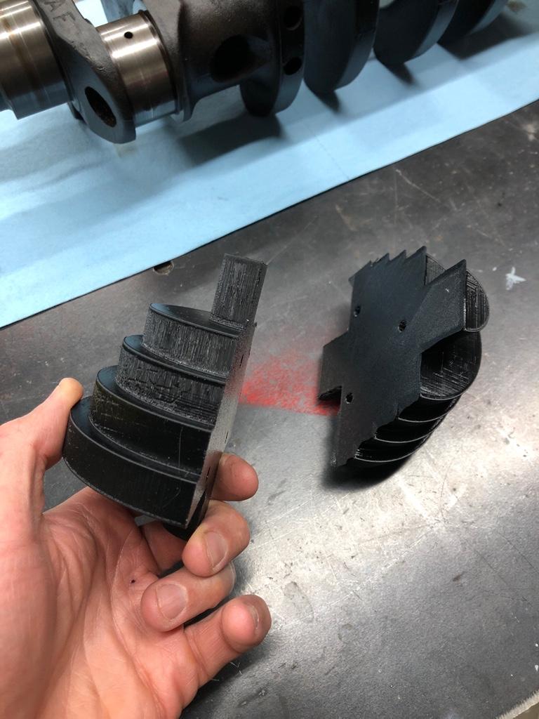
Ended up casting a pulley out of aluminum (4 step). Used 3d printed part as mould

3db9baffe5c8c62fe71add935098e870.jpg

7b8be911552ef342083eeed2cfda7650.jpg


I cast the actual profile on the first one but will use a square stepped blank for my next one as you need to machine it regardless and may as well get a perfect finish with no inclusions

Here is the blank for any future recasts

bd652fb76ae004fd3f3c9159ac9169fd.jpg


Sent from my iPhone using Tapatalk
 
Last edited:
The 1 phase motor measures 0.865 and the 3 phase motor measures 0.8735. Different size keys as well:mad:

Ahh, the old metric vs imperial strikes again:
22mm -> 0.86614
7/8” -> 0.875

Bets, the key(way) is also metric; probably 5 or 6mm vs 1/4 in the 3 phase motor.

Not to poke fun at your struggles, Craig, I’ve been there many times and totally understand your frustrations.

So, over time, I have made both 22mm and 7/8” shafts / arbours so that I can use the NOS milling cutters (which tend to be 7/8”) and the new, offshore, ones as well (they are usually 22mm)

I very much like @kevin.decelles idea: you may need that OEM combo yet in case you need to make a bracket or something before the new 3 PH motor is fully installed on your mill.
 
At the risk of exposing my complete inexperience, other than keeping the original pulley intact, is there a reason not to bore it out to .875"?
 
At the risk of exposing my complete inexperience, other than keeping the original pulley intact, is there a reason not to bore it out to .875"?

It sure isn't much of a difference is it?

I would prefer not to mod the pulley, just to keep the original single phase motor/pulley set intact. The key way on single phase 22mm motor shaft is significantly larger as well. 7mm v.s. 4.65 mm (3/16). But that's easy enough to work around. If push came to shove as a work around I would rather see the motor shaft turn down.

With luck I'll find a 4 step 7/8" bore pulley that's close to the original. The search begins.
 
Last edited:
So, after looking for pulley options I think what I want to do is reduce the OD of the $60 3 PH motor by 0.0085" and use the current pulley. What are my options for doing this?

Do you think I would get away with simply spinning the motor shaft against a file?
 
Probably would work. Not very accurate.

I would bolt the motor to the mill table, tram it, put a HSS tool (a broken drill bit sharpened to suit would work) in the spindle (that is locked to stop rotation of the tool), run the motor with the VFD so you can control the speed, and nibble off the 4 thou per side. Then polish the shaft and make a suitable stepped key.

Or you could disassemble the motor and turn the rotor between centres on your lathe...
 
Back
Top