Former Member
Guest
Yes sort of, basically thin the corners to allow flex there.
Yes sort of, basically thin the corners to allow flex there.
What can't the orange blocks just float? I think because the orange blocks do two things. The first is clamp the fingers from both ends against the middle vise jaw block. The second though is I think the red bar will tend to flex or vibrate up down and back/forth. Having the orange block locked in place I think would minimize that movement.Hey @Janger, I've gone to bed but noodling your problem. I've forgotten what it is you are trying to do here. Can you point me to the goal?
Even thinking on it for a while hasn't changed my view. Your setup is only clamping on the screw leg. All the other legs are way stronger than the screw and are not going to clamp anything. Even if they bent, the overall length will exceed remain the same. It really isn't like a band that slips. It's more like blocks that won't compress. And even if they could, the center block is weaker than they are so it will still be loose.
Even cutting slits all the way around (inside or outside) will not likely solve the compression/bending issue because of the square shape. But it will help.
You might gain significantly though by using two screws on an angle. Essentially pulling two V blocks together. That way each screw acts on two legs and all legs can be shortened to clamp the center block.
The second though is I think the red bar will tend to flex or vibrate up down and back/forth. Having the orange block locked in place I think would minimize that movement.
@JangerClamping along the blue lines is to resist the force of the part, and the resistance through the hole should be greater...
I had intended (but I probably forgot to mention that it should be relieved along the red lines. I hope this is a little better explanation.
View attachment 23373
Thx John, 'cause I'm still not 'getting' it. From the other pictures, the red bar went 'through' the fingers, not sure where the clamping force comes from. We can take this offline -- I don't want to derail this great thread.I’ll post a clearer explanation tomorrow.
Thx John, 'cause I'm still not 'getting' it. From the other pictures, the red bar went 'through' the fingers, not sure where the clamping force comes from. We can take this offline -- I don't want to derail this great thread.
Thx John, 'cause I'm still not 'getting' it. From the other pictures, the red bar went 'through' the fingers, not sure where the clamping force comes from. We can take this offline -- I don't want to derail this great thread.


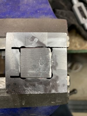
Ok here is how this is supposed to clamp the fingers. First picture shows the red bar it is 0.75"x0.75". You can see it is slightly inset against the fingers. Now look at the second picture. The orange block is is 1x1x1". Bolts go through it into the red bar. Because the red bar is smaller and shorter this means as the orange block is tightened against the red bar the orange block pushes against the fingers squeezing them against the green center part of the vise. The other end of the red bar is the same, the orange block at the other end is also tightened in the same manner. Both orange blocks then squeeze the fingers against the immovable center block. see picture 3 to see the vise jaw block.
View attachment 23389
View attachment 23390
View attachment 23391

I don't have any other drawings yet - just this 3d model. Yes this is all Fusion 360. @Dabbler was trying to use Fusion 360 on an older machine - the limiting factor seemed to be RAM. 8GB just wasn't enough. I have 16GB on my 5 year old macbook pro laptop and it works pretty decent.@Janger, glad it works!
What I am keenly interested in at this point is how the entire assembled vise works. Do you have any drawings of that yet?
Are you using Fusion 3D? I think I may have solved my problem there. I was reading about @Dabbler rescuing an old gaming laptop for his needs and I realized one of my sons has one gathering dust. I may need to add memory, but with a gaming heritage I'm guessing it will run Fusion. It would be nice to have that capability in my shop.