• Scam Alert. Members are reminded to NOT send money to buy anything. Don't buy things remote and have it shipped - go get it yourself, pay in person, and take your equipment with you. Scammers have burned people on this forum. Urgency, secrecy, excuses, selling for friend, newish members, FUD, are RED FLAGS. A video conference call is not adequate assurance. Face to face interactions are required. Please report suspicions to the forum admins. Stay Safe - anyone can get scammed.
  • Several Regions have held meetups already, but others are being planned or are evaluating the interest. The Ontario GTA West area meetup is planned for Saturday April 26th at Greasemonkeys shop in Aylmer Ontario. If you are interested and haven’t signed up yet, click here! Arbutus has also explored interest in a Fraser Valley meetup but it seems members either missed his thread or had other plans. Let him know if you are interested in a meetup later in the year by posting here! Slowpoke is trying to pull together an Ottawa area meetup later this summer. No date has been selected yet, so let him know if you are interested here! We are not aware of any other meetups being planned this year. If you are interested in doing something in your area, let everyone know and make it happen! Meetups are a great way to make new machining friends and get hands on help in your area. Don’t be shy, sign up and come, or plan your own meetup!

New to me Ammco 7" Metal shaper

Congrats on the first run, i also saw that you found some tool holders. Saves me from rooting around for the ones i know i have someplace.

Thank you for the thought!

Ya, I found some just down the street from our meetup. Considering how hard they are to find and where they were, I got really really lucky!
 
maybe have to fill that tool chest stand with some tools, or a bag of concrete. Maybe the epoxy kind, I hear it’s popular.

The chest isn't empty. It's actually fairly heavy. The problem is that Ram inertia. The other issue is the wheels.

I am thinking that I'll lift the chest onto pads beside the wheels. If that doesn't work, I'll have to resort to buying or building a separate stand.
 
But first chips first.

Beautiful finish. Camara lens makes it look ugly, but it's gorgeous......

View attachment 63884

But, I need some shaper advice here....

View attachment 63885

Look at the leading edge. Looks like it digs in a wee bit deeper when it first connects and then bounces out to finish the cut. And what's with the wee bit of shatter as it leaves the cut on the left side? What is going on?
Not sure for certain what is going on, but I have a question about the setup....
Is it feeding on the retracting or is it possibly feeding during the cut. When you are setting the feed rate, it can be set on either side of center. One side is for feeding while cutting to the left and the other side is for cutting to the right.... It almost looks like it is trying to push the feed during the cut.
 
Thank you for the thought!

Ya, I found some just down the street from our meetup. Considering how hard they are to find and where they were, I got really really lucky!
That wasn't luck, that's the universe telling you that they were meant to be yours..... :cool: Good things come to those who do good.:rolleyes:


. Not really sure why you got 'em though.... ;):p:cool:
IMG_0485 (1).gif
 
Not sure for certain what is going on, but I have a question about the setup....
Is it feeding on the retracting or is it possibly feeding during the cut. When you are setting the feed rate, it can be set on either side of center. One side is for feeding while cutting to the left and the other side is for cutting to the right.... It almost looks like it is trying to push the feed during the cut.

I don't know enough yet to answer your question with certainty.

I had thought it was only possible to feed during the retract. I didn't know there was any adjustment to that. I was only aware that I could set the table feed direction on the little cap on the feed system. It has an arrow that feeds the table left or right. There is also an adjustment for the feed rate.

But you remind me of another issue I noted but have not explored yet. The cutter seems to want to wander to the left (with respect to its path). For now, I think this is low rigidity. And in case you are wondering, all the locks are engaged except the table feed.

I have also noted that HSS doesn't seem to do either one.
 
20250429_192006.jpg

Not the best picture, and pay no mind to the broken out piece of tee slot (would like to hear the story on how they did that...)
However, it should show what I am talking about.... If I were to loosen the knob and move it towards the broken out section the feed would increase, and if I move it to exactly center, there would be no feed. However, if I move it to the other side of the center, I am now 180 degrees out on the feed, ie: feeding on the forward stroke, unless of course I change the direction of travel at the same time.
 
Not the best picture, and pay no mind to the broken out piece of tee slot (would like to hear the story on how they did that...)

Prolly putting the slot in tension instead of compression.

However, it should show what I am talking about.... If I were to loosen the knob and move it towards the broken out section the feed would increase, and if I move it to exactly center, there would be no feed. However, if I move it to the other side of the center, I am now 180 degrees out on the feed, ie: feeding on the forward stroke, unless of course I change the direction of travel at the same time.

I think I have to study the mechanism a lot closer. That may or may not be possible on my AMMCO.

Thanks for bringing that to my attention. I would never have thought to look for such a thing.
 
But first chips first.

Beautiful finish. Camara lens makes it look ugly, but it's gorgeous......

View attachment 63884

But, I need some shaper advice here....

View attachment 63885

Look at the leading edge. Looks like it digs in a wee bit deeper when it first connects and then bounces out to finish the cut. And what's with the wee bit of shatter as it leaves the cut on the left side? What is going on?
Yeah, sometimes it does that. It's pretty much a relic from that the shaper you are using, is a pretty light weight piece of gear, and does require that you allow for both the various bits of tolerance that add up, as well as that you accept the flexibility of a lightweight machine tool.

Plan your workpiece around this happening, by adding a little sacrificial material that can cut away the 'injury', or simply accept it, if it doesn't change the usefulness of the part being produced.
 
Prolly putting the slot in tension instead of compression.


I think I have to study the mechanism a lot closer. That may or may not be possible on my AMMCO.

Thanks for bringing that to my attention. I would never have thought to look for such a thing.
You can tell pretty quickly by looking at the feed rod, it should be ratcheting back while the ram is moving forward.....
I am not sure about the Ammco either, but both my bigger shapers essentially operate the same way.....
Looking at the picture again, it almost looks like you had a pretty coarse feed rate, or it might just be the camera angle......
I'm looking forward to hearing how you respond to the surface finish when you put a shear tool in, a fine feed, and a slow ram speed. You almost enter the realm of reflection. ;)
 
I'm looking forward to hearing how you respond to the surface finish when you put a shear tool in, a fine feed, and a slow ram speed. You almost enter the realm of reflection. ;)

I don't think that day is far away......

Since the entire length of the tool edge will be cutting, I am wondering what the angle should be, what the length should be, what the width should be, and what the feed rate and depth of cut should be...... It's a lot of variables.
 
Take a look at this photo, it shows the adjuster for setting the amount of table travel per stroke and the direction of travel. Just to the left of the driven pulley entering the shaper and a bit higher, is a nut on what appears to be on a shaft. Behind the nut is a slot, loosen nut a bit, now this slot is able to be moved, center the slot and there is no table movement, put slot all the way to one side and table will move one way, don’t change the ratchet direction, move the slot the other way and the table will move the other way.
Yes, the ratchet dog will change the direction the table moves, however the table should move when the ram is on the non cutting/return stroke, I say non cutting stroke as the ram “ could” be set up to cut on the back stroke, do not know why it would be, BUT.
Moving the table when cutting results in a tapered cut and much higher forces on the screw and ratchet mechanism.
I hope this helps @Susquatch. @140mower also talks same things in the above posts
If this is not clear, I can try to muddle and muddy up the waters up more. LOL, choke, gasp, up for air.
There is also a second adjuster for setting amount of table movement with the knurled knob and it’s slotted track on the pivot arm.
 

Attachments

  • IMG_0028.jpeg
    IMG_0028.jpeg
    1.7 MB · Views: 9
Last edited:
You can tell pretty quickly by looking at the feed rod, it should be ratcheting back while the ram is moving forward.....

I had a good look at how it all works. It's not obvious at all and some of it isn't even mentioned at all. It will take me a while to sort through everything.

The good news is that your quick check works out ok for the cut I was taking. Well, I say good news but I suppose bad news would have been better in terms of fixing the issues. Bottom line is that my feed happens, during the return stroke, not during the power stroke.

It seems rather obvious to me that rigidity in this little shaper isn't going to be stellar. There may be lots of things like this that need to be compensated for or just outright accepted and lived with.

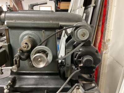
One thing I noticed right away when I was investigating your suggestions. There seems to be four ways to adjust the feed rate. A, B, C, & D in the photo below.

20250430_110707.jpg

A has 4 positions R, L, and 2 neutral. The R position moves the table Right, and the L position moves it Left. The neutral positions allow the user to move the table manually. Moving it manually in L or R, does not appear to be healthy.

The B adjustment just seems to clock the feed arm relative to the feed drive. I suppose that there are preferred relative locations that maximize or minimize the relative translation. It works as is and seems to be pretty close to 1 to 1 so I've left it alone as is.

The C & D adjustments are quite interrelated. Both will increase or decrease the feed stroke which increases or decreases the feed rate. C is a plain linear adjustment that even has numerical markings on it.

D is the most interesting. There are no graduations and no directional indicators. However, moving the eccentric to one extreme or the other changes the timing of the feed to coincide with the direction of the Ram - feed during power stroke or feed during retract (what you referred to in your earlier note). There are no markings to show which is which. I suspect you should normally choose which one you want at the same time as you adjust the length of the Ram stroke. However, you can also set the eccentric to intermediate positions ranging from full eccentricity to zero eccentricity to full opposite eccentricity. I gather the choice is best used simply to fine tune adjustment C.

Comments? Did I miss anything or mess anything up?
 
This is the table step over amount and step over ram direction adjustment on a 8" Peerles shaper. Amount is controlled by how far the connection link mount is from the center of the slotted drive wheel. Direction is controlled by which side of center the connecting link mount is on the slotted drive wheel.

Your Ammco shaper will pretty much work the same way.

1746032102781.jpeg
 
Last edited:
D is an either/or position. Always set it to one extreme or the other. It determines when the feed occurs as in on forward or back stroke. aka Eccentric feed nut.
C sets the cross feed amount. 0.003 to 0.018"
B adapts the feed arm to height of bed.

Page 6 of manual is what you need. Terrible manual, they taught the Chinese how to write poor manuals IMHO :-)
 
You may want to be careful of "B", make sure the link does not bind on the ratchet housing when moving, can be adjusted by changing link length.
"C", I only use to adjust amount of feed, fine and course amount. "D", I use to course set feed amount AND to change table movement advance to return stroke of ram. Being as table can move either way and cutting can take place on either side of project, eg. cutting on left side (facing machine at table end), table feeding towards left, or cutting on right side of project, with table advancing to right side.
 
Another question.

It seems to me that the ratchet in the power feed limits the feed rate settings to multiples of the pawl clicks. So the minimum feed isn't really the settings, it's one click which is about 15° or so. Does this sound reasonable? Would a slight gibb tightening change this?
 
Back
Top