-
Scam Alert. Members are reminded to NOT send money to buy anything. Don't buy things remote and have it shipped - go get it yourself, pay in person, and take your equipment with you. Scammers have burned people on this forum. Urgency, secrecy, excuses, selling for friend, newish members, FUD, are RED FLAGS. A video conference call is not adequate assurance. Face to face interactions are required. Please report suspicions to the forum admins. Stay Safe - anyone can get scammed.
-
Several Regions have held meetups already, but others are being planned or are evaluating the interest. The Calgary Area Meetup is set for Saturday July 12th at 10am. The signup thread is here! Arbutus has also explored interest in a Fraser Valley meetup but it seems members either missed his thread or had other plans. Let him know if you are interested in a meetup later in the year by posting here! Slowpoke is trying to pull together an Ottawa area meetup later this summer. No date has been selected yet, so let him know if you are interested here! We are not aware of any other meetups being planned this year. If you are interested in doing something in your area, let everyone know and make it happen! Meetups are a great way to make new machining friends and get hands on help in your area. Don’t be shy, sign up and come, or plan your own meetup!
You are using an out of date browser. It may not display this or other websites correctly.
You should upgrade or use an alternative browser.
You should upgrade or use an alternative browser.
New 10" X 54" mill ordered.
- Thread starter John Conroy
- Start date
I've read where some people extend or retract the Y dovetail arm so they can make the head rotation with clearance, then return it back with tilt setting so its repositioned over the mill table. But its very shop / encumbrance dependent. I thought of many applications I thought I'd be using my mill in tilt mode, but thus far mostly its stayed in the vertical position for the work I've done. I'm no longer apprehensive about dialing it back in, it's just a bit time consuming. In hindsight I probably could have accommodated a riser block & would have benefitted but there were just too many variables with my floor stand & overhead door rails, I didn't want to guess wrong. I didn't even think far enough down the road about pneumatic tool changer, I use a Milwaukee cordless socket wrench on tippy toes. Some of the forum comments said the manufacturer dimensions were not very trustworthy and/or manufacturer changes castings on the fly, although I think PM actually took the time to measure their machines & document it. The 1P motor on my mill is longer body so sticks up more than the 3P. I think if they offered an inflatable milling machine blowup doll or a 1:1 scale cardboard template in front/side view, people might actually buy it! LoL. I'm confident it will all come together to your satisfaction. We are problem solvers!
Last edited:
I think you're right Rudy. With the knee fully lowered there is 21" from spindle to table top, 3 more than my old mill. If I add the 6" riser block it will put the top of the motor in front of the furnace. For now I'm going to put the riser block aside as I probably won't need it with the extra room under the spindle.


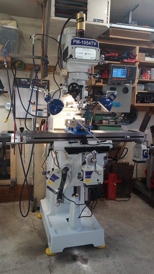
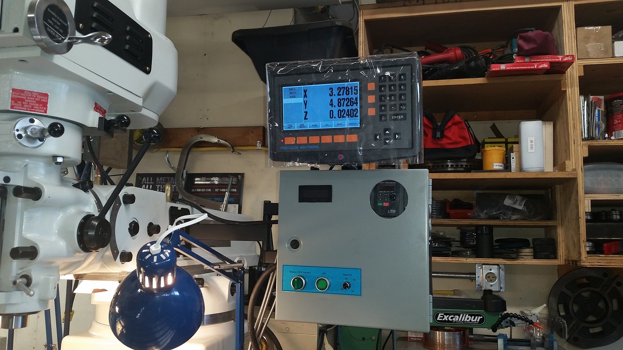
I got started on the DRO today. I made a small bracket so I can mount the display on top of the VFD enclosure and got the X axis scale mounted. There were no screws in the kit so I had to use some of the M5 stainless screw I keeps around for motorcycle work. I successfully drilled and tapped the 6 required M5 holes with no mishaps. The X is usually easiest as the scale gets mounted to a machined surface but I wound up needing a .020" shim behind one end to off set what looks to be one oddball end cap on the scale. With a bunch to messing around I was able to get square within .002" in both planes. I think that's pretty good for a 37" scale.


Installing a DRO is a lot of work and very time consuming if you don't do it often. I installed the one on my old mill but had forgotten. I had to make a run to the bolt house to pick up a bunch more screws but other than that I spent the rest of today installing the Y axis scale and integrated the power feed end stop switch and related hardware onto the same brackets. It turned out pretty well but I forgot to take pictures until I finished. Tomorrow onto the Z axis .


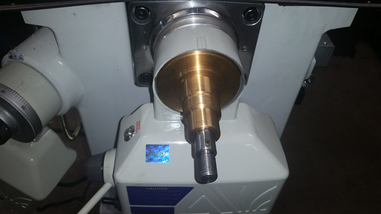
This morning I decided that installing the Z axis DRO scale would involve moving the knee full travel bottom to top at least a few times to measure scale alignment. After I did it once I decided to put a hold on the DRO install while I installed the Z axis power feed. It takes 90 rotations of the knee lift crank to go full travel and my should was complaining after half travel. The power feed 8nstall threw a curve at me when the extensio shaft would not engage the threads on the original shaft. After a bit of head scatching I realized the original shaft was too long and after careful measurements I cut off .600" to make it fit. It went smoothly from that point. I only needed one .010" shim to get the gear mesh set correctly.


After the power feed install I got serious about the Z axis DRO scale. What make this one a challenge is making the scale align perfectly with the knee travel when the column of the mill is tapered top to bottom and front to back. After some measuring trial and error I decided I could deal with the 2 degree angle front to back using an angle block in the milling vise so I went ahead and made the first chips. I dealt with the taper from top to bottom with different height mounting blocks with very narrow contact pads to prevent introducing bends into the mounting bracket. I learned a lot during this exercise, I just hope I can remember it next time I have to deal with a mounting challenge like this. Tomorrow I'll finish the mounting brackets for the read head. Matt sent me some pictures showing how they set up the brackets when they install the DRO a d I'll have to make some custom parts.


Nope just the knee. I have a separate non integrated quill dro to install also.Will the Z-Axis DRO/scale install combine the knee and the quill?
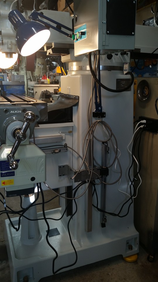
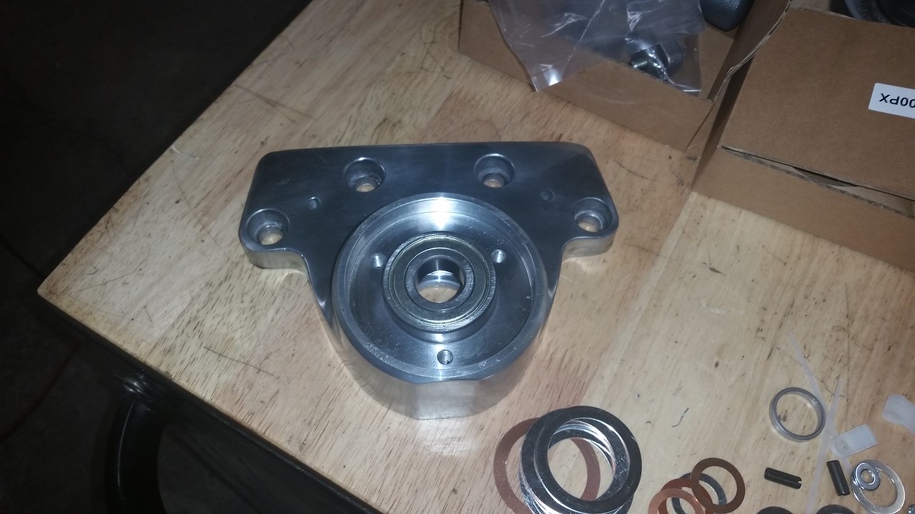
I know it doesn't look like much but this collection of the supplied and shop made brackets for the Z axis scale and power feed stops represents over a day of work. I wanted to keep the power feed stop hardware away from the knee lock handles, it always seemed in the way on my old mill. The cable to the switch is just barely long enough for this type of mounting. Without custom making all the hardware that's about as clean an install as I could come up with. Tomorrow I can install the X and Y axis power feeds.


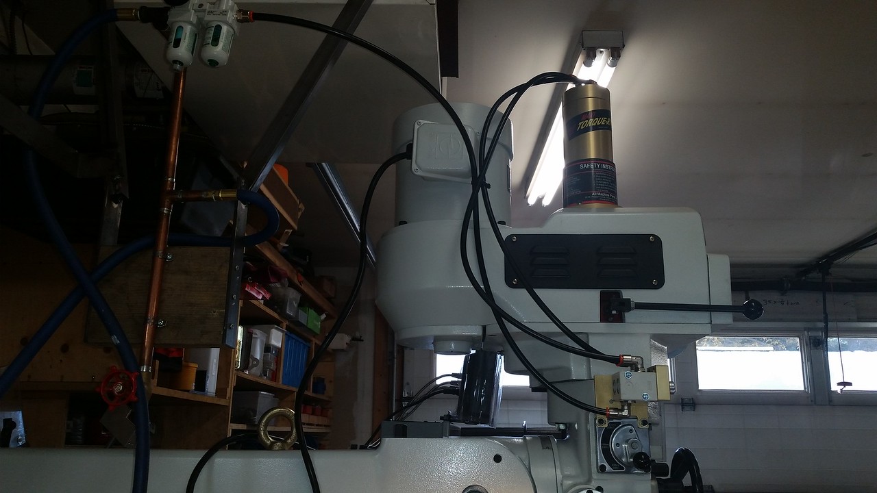
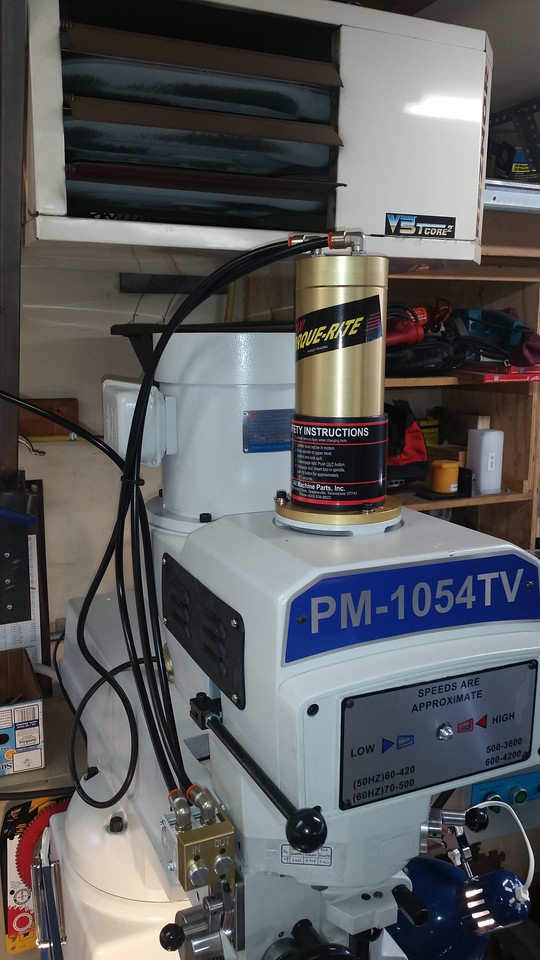
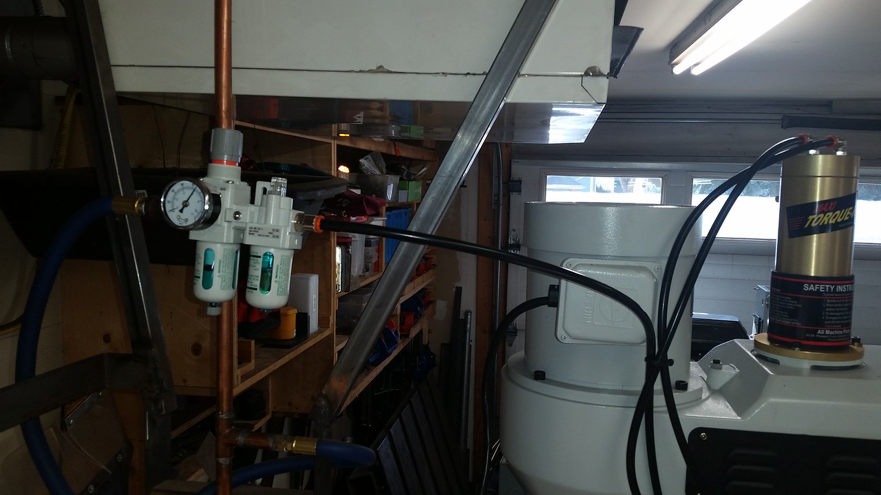
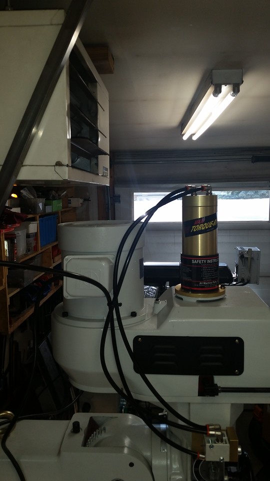
Over the last day and half I got the X and Y power feed units and the power draw bar installed. I'm glad I ordered the power draw bar, even when standing on a 2 step stool I can't see the draw bar, I have to loosen by feel. This Torque-Rite unit is pricey but comes enough hardware to mount it on pretty much every possible Bridgeport or clone you could find. Absolutely every thing I needed came in the box except Teflon tape. It even came with a bottle of air tool oil.
I spent extra time getting the backlash in the power feed drive gears as low as possible while still having some, these unit came with a selection of shims down to .003" thick so it was possible to really dial the backlash down to a low amount. These are the quietest ones I have ever seen, really happy I spent a few extra buck and ordered the Align brand units. I still have to do some work on cable management as it looks like a den of snakes right now and I still have to install the quill DRO. I'm working on a solution for the tachometer speed sensor and magnet mounting but the machine is pretty much ready to go to work. I trammed the head this morning and got it dialed in at less then .0005" deviation on both axes. I need to get some sort of table covers as well, I have already made a couple of marks on that shiny new table. LoL
I also fabbed a couple of mount for my Ikea work lamps. You can't go wrong for $15 each for these things, they even had blue ones to match the blue on the new mill!
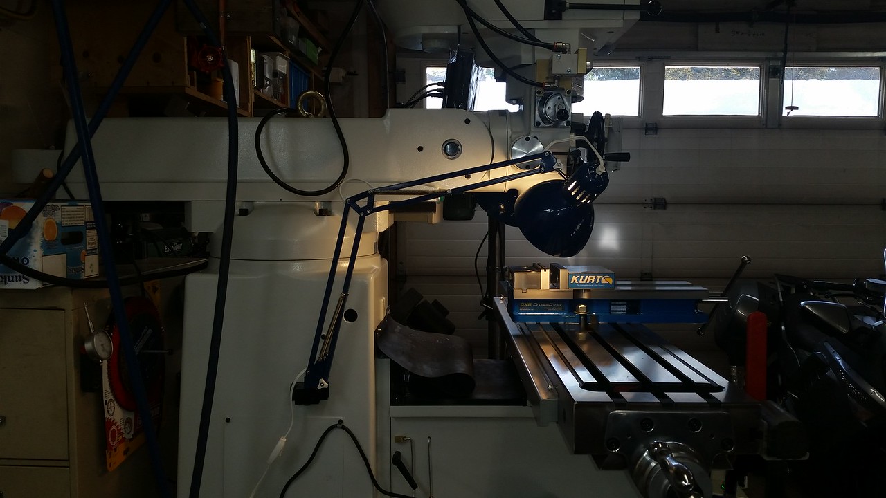
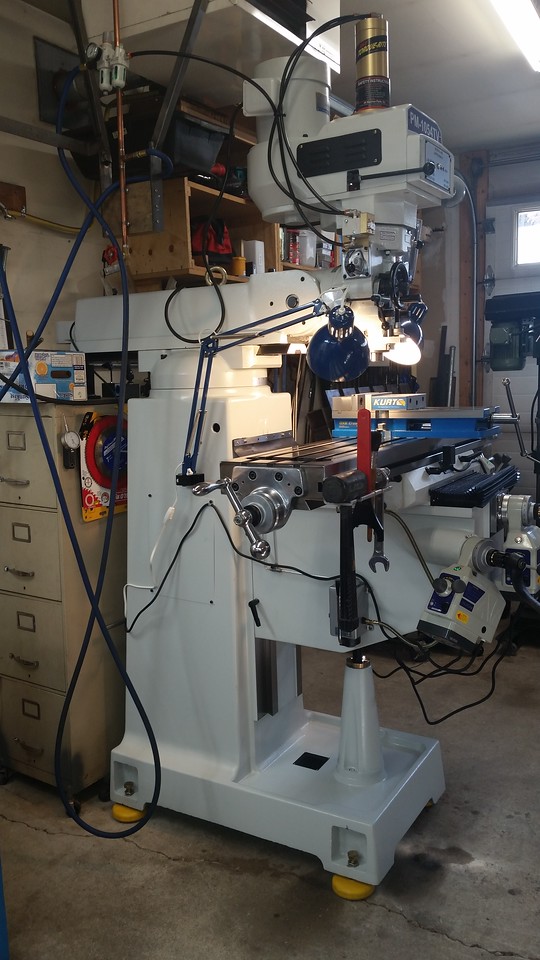
Coming along nicely John! Your ceiling heater lives to heat another day without getting replaced to make way for tool changer haha.
I saw Clough42 just posted a video on his PF conversion to his new PM 935 mill (same model as mine). The way he did/re-did the shims was a bit different. Unlike you, I had PF installed when I purchased. Which is good because its done, but bad because I didn't get to learn & be picky (and oh ya, costs money). But now that I see the operation in video, there are quite a few important gaps & shims that need to be set up properly in sequence. Not pertaining to your build but interested to hear your comments if you have time to view. I'm glad I took your advice on the knee PF, Crank-o-rama would get old in a hurry.
I saw Clough42 just posted a video on his PF conversion to his new PM 935 mill (same model as mine). The way he did/re-did the shims was a bit different. Unlike you, I had PF installed when I purchased. Which is good because its done, but bad because I didn't get to learn & be picky (and oh ya, costs money). But now that I see the operation in video, there are quite a few important gaps & shims that need to be set up properly in sequence. Not pertaining to your build but interested to hear your comments if you have time to view. I'm glad I took your advice on the knee PF, Crank-o-rama would get old in a hurry.
Last edited:
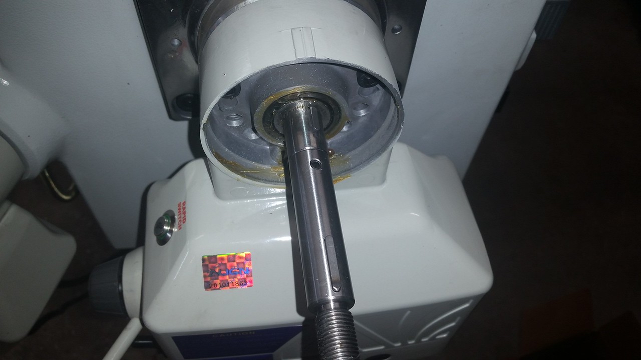
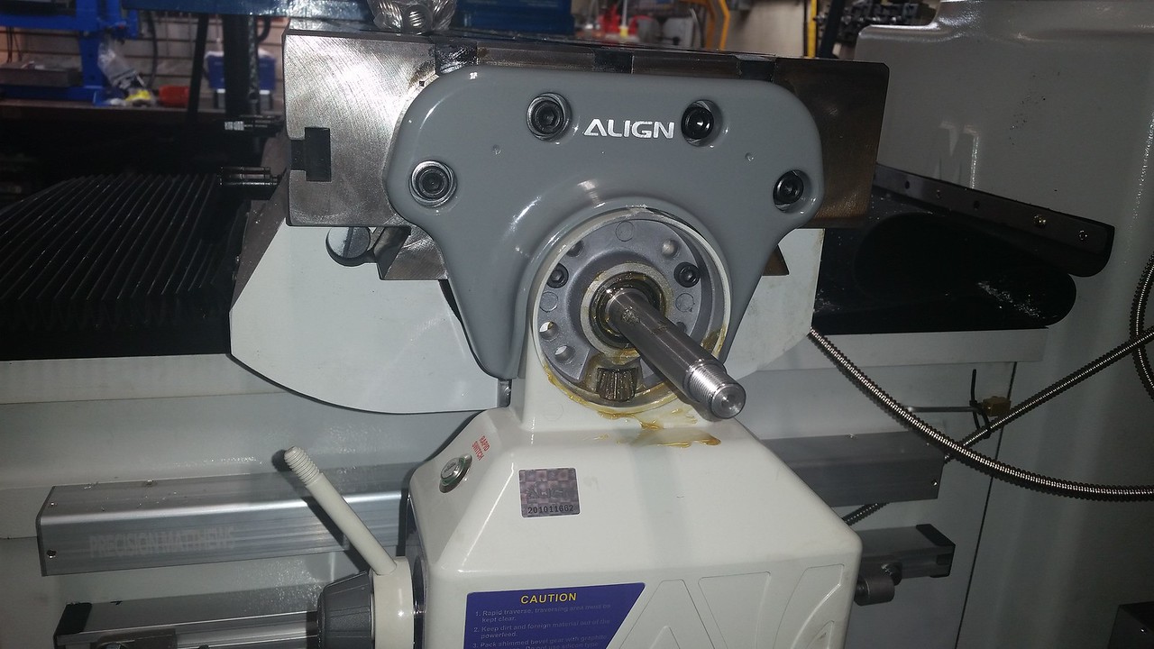
Thanks guys. I did watch that Clough42 video Peter. I found that my inner bearing race is a tight interference fit on the lead screw. I had to drive it on with a brass punch so there is no worry of it spinning on the shaft. For that reason I didn't use that small spacer behind the race and the bearing is fully supported by the race. I had actually made a sheet metal spacer like James did before my machine was here but didn't use it.
You can see the inner race is further in than the shaft shoulder and the bearing rollers are fully supported by the race.

You can see the inner race is further in than the shaft shoulder and the bearing rollers are fully supported by the race.
Last edited:
The Y axis power feed was a bit challenging because you have to drill a hole for the roll pin through the extension shaft and the threads of the original shaft with a hand drill. I held the shaft with a clamp to keep it from turning while I drilled it.


